Technical Paper
The design and application of deep water offshore cathodic protection systems: Some practical considerations
by Jim Britton and RE Baxter (1999) from Corrosion99

Abstract
There have been a good number of deep water projects completed in the Gulf of Mexico over the last 10 years, and the types of structures deployed have varied widely, from fixed platforms, floating production systems, tension leg platforms, subsea completed systems, pipelines and umbilicals. This paper will discuss some practical guidelines which will ensure the success of cathodic protection systems in these environments such as materials to avoid, anode compositions for deep cold water, the use of coatings, tips on successful inspection and monitoring of in-place systems and some guidelines for specification writing. Some aspects of the importance of material quality control are also discussed, as well as some new developments which may affect how the cathodic protection designer tackles future projects.
Introduction
Coatings, backed up by cathodic protection (CP), is the corrosion control method of choice for steel structures exposed directly to seawater in the deep ocean. The fixed structures associated with oil and gas production are most often protected by galvanic anodes as opposed to impressed current CP systems. Galvanic anodes are preferred on these structures because of the high degree of reliability normally associated with such systems, and this reliability translates directly to a reduction of risk. The consequences of a corrosion-related failure in this type of equipment could be economically devastating to the operator and could have potentially serious environmental impacts. Therefore, we must ensure that cathodic protection systems for deep water work right, first time, every time with no exceptions!
Basic design tips - design conservatively: The cost of many deep water projects may be measured in hundreds of millions of dollars, but the cost of the galvanic anodes for such projects is usually measured in tens or hundreds of thousands. CP is cheap! Use it wisely because over-optimizing CP designs can lead to under-design. If there is no weight constraint, a high level of system redundancy should be routinely applied. 30% more anode material than the worst case estimate makes a great deal of sense in most cases.
Conservative design practice is particularly important when dealing with deep-water pipelines or flowlines. The usual bracelet anodes fitted to the pipelines may be damaged during the pipeline installation. This could render them inoperative, so be sure to make adequate allowances for this potential damage. The use of protective cast polyurethane tapers around anodes has gained much popularity in recent years. These cast-in-place tapers are relatively inexpensive and provide excellent protection to the anode from impact or mechanical snagging during the pipe lay operation.
Basic design tips - coating deterioration: Depending who you ask, you will receive differing opinions on how a coating performs in long-term seawater immersion. What is the initial damage percentage? What is the projected bare area percentage at the end of the design life? The Det Norske Veritas (DnV) RP 8401 (1993) "Cathodic Protection Design" gives some extremely conservative recommendations in sections 6.4 and 6.5. Using this code would have some coating systems 100% failed in less than 20 years. There are escape clauses - e.g. section 6.4.7 - that reads; "Operator's experience of a specific paint coating system may justify the use of less conservative coating breakdown factors than specified in this document." Common sense, with a conservative approach should rule.
Basic design tips - understand the environment: The deep ocean environment requires special attention when designing CP systems, Early designers quickly found out that trusted shallow water design criteria did not work in deep water. Other authors in this STP have covered in detail the reasons why the CP design criteria should be different. There are three major factors to bear in mind:
1. Water temperature - Temperature decreases as depth increases; temperature directly affects the electrical conductivity / resistivity of the seawater. Temperature directly affects the morphology of protective calcareous deposits formed at the cathode surface.
2. Water resistivity - The specific resistance of the seawater increases as temperature decreases. This directly affects the electrical resistance between anodes and the seawater, which, in turn reduces the CP current output from a typical anode. Lower output means that more, smaller, anodes are needed to provide the desired current.
3. Calcareous deposits - Calcareous deposits are the result of the electrochemical reactions associated with cathodic protection. These deposits, formed on the cathode, have the effect of reducing the current density required to maintain polarization. The current density requirement is the measure of "how much CP" is required in a given situation. In cold water, calcareous deposits form more slowly and are generally less dense than those formed under similar conditions in warmer water. The less dense deposits require a higher current density to maintain polarization.
In summary, designing CP for deep, cold water versus shallower, warmer water, requires the following changes in design approach: Use higher current densities and use higher seawater resistivity values to compute anode current output. These two factors go a long way to justifying the wide use of coatings on deep water projects which are typically absent in shallow water.
Basic design tips - use quality anodes:
Aluminum anodes - More than 95% of aU anodes used in deep water CP systems are Aluminum (AI) alloyed with zinc (In) and Indium (In). This gives us the Indium activated Aluminum anode. This alloy was developed in the 70's and is the preferred anode for deep water applications for the following reasons:
1. It is lighter than zinc and has a much higher galvanic capacity.
2. It has a higher driving potential than the alternate Mercury (Hg) or Tin (Sn) activated alloys. This is needed to offset the higher seawater resistivity.
3. The Indium activated material will work predictably in seawater or when covered in seabed mud, silt or sand.
Table 1. Shows a comparison of the properties of commonly available generic anode types.
While Al-In-Zn anodes have generally performed very well in ambient temperature seawater (65°P - 75°P), laboratory and field tests have shown that some alloys have been slow to activate, or have failed to activate in cold water (35°P - 45°P). If an anode fails to activate, it contributes nothing to the CP system. The consequences of this occurrence are obvious! Most anode manufacturers now have modified chemistries designed specifically for cold water, but will only supply them if the specifications require them.
Table 2. Compares a generic chemical composition typically used for ambient temperature seawater, with one tailored for cold water. While the differences appear small, they can be crucial in certain cases.
Table 1
Galvanic anode properties
| Property I Alloy | AI-Zn-In | AI-Zn-Hg | Zinc Mil. 180001 H |
|---|---|---|---|
| Potential (-) Volts vs Ag/AgCI | 1.08 | 1.05 | 1.05 |
| Galvanic Capacity A. Hrs. lIb. | 1150 | 1280 | 355 |
| Galvanic Efficiency % | 85 | 95 | 95 |
| Mud Performance | Good | Unpredictable | Good |
Table 2
Anode chemistry for cold water
| Element | Typical | Cold Water |
|---|---|---|
| Iron (Fe) | 0.10% max | 0.007% max |
| Zinc (Zn) | 2.8-7.0% | 4.75 - 5.25% |
| Copper (Cu) | 0.006% max | 0.005% max |
| Silicon (Si) | 0.20% max | 0.10% max |
| Indium (In) | 0.01- 0.03% | 0.015 - 0.025% |
| Cadmium (Cd) | Not Specified | 0.002% max |
| Others (each) | 0.02% max | 0.02% max |
| Aluminum | Remainder | Remainder |
Anode specifications - The realization that a specific anode type of a specific chemistry is required is only half the solution. Getting the correct material on the equipment requires somewhat more diligence. A well-written anode specification is crucial in getting the desired product. Apart from the obvious dimensional, composition and weight requirements, it is wise to specify that the electrochemical testing be performed in artificial seawater maintained at the anticipated minimum service temperature. All the major domestic anode foundries have this capability and are quite used to complying with these requirements even though they are not spelled out in any industry standard or recommended practice at this time.
Helpful standards - The National Association of Corrosion Engineers (NACE) has some documents that are very helpful in developing a good anode procurement specification. Be aware that some of the cold water requirements are yet to be added to these documents at the time of this writing.
• NACE RP-0492-92 "Metallurgical and Inspection Requirements for Offshore Pipeline Bracelet Anodes"
• NACE RP- 0387-90 "Metallurgical and Inspection Requirements for Cast Aluminum Sacrificial Anodes for Offshore Applications"
• NACE TM-O190-90 "Impressed Current Test Methods for Laboratory Testing of Aluminum Anodes"
• NACE Report 7L-I92 "Cathodic Protection Design Considerations for Deep Water Structures"
Note: Updates of these standards can be monitored on the NACE International Internet Site at www.nace.org.
Inspection - Remember to always "expect what you inspect". On projects of this scale, the cost of a qualified anode quality assurance inspector is minimal and should be included as a matter of course.
Some pitfalls to avoid
Electrical discontinuities - Many subsea structures currently being installed are complex mechanical devices with hundreds of individual components and many moving parts. A typical subsea wellhead tree is shown (Figure 1). The anodes for these devices are typically welded to the support frame(s). If all the pieces of the assembly are not electrically tied, with a sufficiently low resistance, to the frame, then the unbonded component is free to corrode at whatever rate applies to that material in seawater. Some common causes of discontinuity are:
1. Bolting together coated components. The coating provides sufficient dielectric strength to often render both the fasteners as well as one of the bolted components isolated from the anodes.
2. Fluorocarbon coated fasteners, used to provide predictable torque response, are often left isolated because the fluorocarbon coating is dielectric. The fastener coating is usually damaged during make up and is free to corrode.
3. The use of articulated joints often results in a discontinuity across the articulation mechanism.
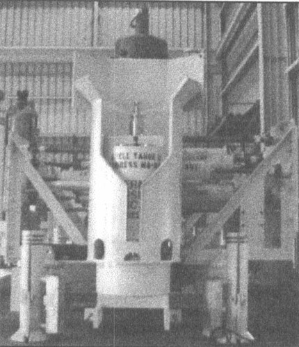
Figure 1 - Typical subsea wellhead assembly
Continuity testing - Most subsea developments have a phase called System Integration Testing (SIT). All the various components of the system are stacked up in a simulation of the offshore installation. This is an excellent time to verify electrical continuity from a common point on the frame (where the CP source is attached), to each individual component on the assembly. A standard multi meter can be used to check the resistance. The author's company recommends that a value of O.IQ or less be verified (excluding test lead resistance). Discontinuities (and there will usually be some), can be fixed onshore quite easily. (Figure 2) shows a typical discontinuity found during an inspection.
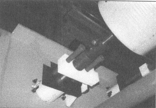
Figure 2 - Discontinuity through a linkage mechanism
Continuity fixing - There are several options to take care of discontinuity problems which have been used successfully.
1. Tack weld across bolted joints
2. Use stainless steel wire jumpers between components
3. Use star (serrated) washers under bolt heads
4. Remove paint coatings under bolt heads
5. Use conductive fastener coatings
6. Locate anodes on more components.
Material incompatibilities - The vast array of materials and corrosion resistant alloys being used on these projects can cause problems. It is important to review all materials that will be cathodically protected for their susceptibility to hydrogen embrittlement at the expected electrochemical potentials. Materials that should be closely checked include some Titanium alloys, some stainless steels (400 series for example) and 17-4 PH. It is often difficult to prevent components from receiving CP even though the material selection engineer may not have intended it.
Complex geometry shielding - Some of the components used to make subsea pipeline connections are extremely intricate mechanical devices. It is important to remember that large areas of uncoated steel (albeit stainless steel) in metallic compartments may be subject to cathodic shielding, and may not receive sufficient CP current to adequately provide protection. Care should be taken to ensure that these areas are provided with anodes inside and outside the compartment.
Don't forget the mud - The pilings used on some subsea facilities represent a huge area of bare steel as compared to the area of bare steel exposed at coating defects in the water phase. Even though these areas require significantly lower current densities the large area can amount to a disproportionately high anode weight requirement. Be sure that these areas are accounted for conservatively. Consider the use of TSA coatings on the pilings to reduce this current requirements to manageable levels.
Be ROV friendly - At extreme depths >1000 feet, all work on the facilities will have to be performed by a Remotely Operated Vehicle (ROY). These machines, while continually improving, are still machines with limited dexterity and a tether / umbilical. To keep the cathodic protection design ROV friendly, follow these simple steps:
1. Locate anodes in areas that will not interfere with ROV operations, and avoid designs that introduce potential snag points for the tether.
2. When locating ROV test points, include a grab rail for the vehicle to hold while monitoring the point. This will reduce wear and tear on the ROV's manipulators and on the monitoring equipment (Figure 3) shows a typical CP test point on a tree.
3. For potential monitoring, provide clearly marked, bare steel test stab locations. The high quality coatings used on many of these facilities do not allow stabbing probes to easily penetrate.
4. When specifying CP probes or Current probes select a mount that will easily fit the ROV manipulator and which will require minimum interface to the ROV electronic and fiber optic systems. (Figure 4) shows a typical deep-water self contained CP probe.
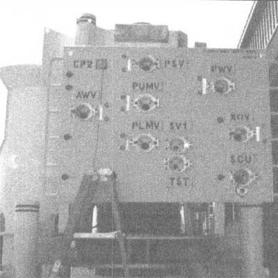
Figure 3 - CP test point on top left corner of ROV panel- note grab rail
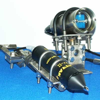
Figure 4 - Historical CP readings
Summary
Deep water projects are now common in the Gulf of Mexico but engineering standards have not kept pace with development. Hopefully, this paper will provide some guidance on the important issues to consider when embarking on a cathodic protection sysytem design. Maintain a conservative approach and insist on top level quality assurance, and always remember that it is much easier to fix a problem on the beach than it is in 3,500 feet of water.
The Design and Application of Deep Water Offshore Cathodic Protection Systems: Some Practical Considerations
by Jim Britton and RE Baxter (1999) from Corrosion99
ABSTRACT
There have been a good number of deep water projects completed in the Gulf of Mexico over the last 10 years, and the types of structures deployed has varied widely, from fixed platforms, floating production systems, tension leg platforms, subsea completed systems, pipelines and umbilicals. This paper will discuss some practical guidelines which will ensure the success of cathodic protection systems in these environments such as, materials to avoid, anode compositions for deep cold water, the use of coatings, tips on successful inspection and monitoring of in place systems and some guidelines for specification writing. Some aspects of the importance of material quality control are also discussed, as well as some new developments, which may affect how the cathodic protection designer tackles future projects.
Want to receive an email when Deepwater publishes new corrosion-related technical papers, case studies, and more? Sign up for our Corrosion Newsletter using the form below. You can unsubscribe at any time.