Quality assurance of aluminum sacrificial anodes for offshore applications
by Jim Britton (1993)

Abstract
In recent years there has been a far greater emphasis placed on quality assurance / quality control within the oil and gas industry, and this has filtered down to the cathodic protection supply sector within the offshore market. The need for quality aluminum anodes is obvious, especially when deep water projects are being considered. This trend toward higher-quality control levels has resulted in more third-party inspection work and better defined quality-test procedures [1]. This paper will focus on the practicalities of quality control and will highlight some of the problems which have been encountered.
Introduction
When offshore aluminum anodes are manufactured for pipelines and platform applications, there are four basic critical inspection areas. The first is the quality of the raw materials, core steel, primary aluminum and master alloys. The second is the chemical composition of the finished anode casting. The third is the electrochemical performance of the anode alloy and the fourth is the physical quality of the product. A typical anode inspection will address all four of these areas to some degree. The anode manufacturing specifications are typically different for each major purchaser; the tolerances of the specifications are still quite varied. This paper will concentrate on the specifications which the writer considers to be the most important.
Critical performance issues
When a galvanic anode cathodic protection system is designed, there are certain performance-related parameters which are assumed for the anodes. Obviously, it is these parameters which must be checked and verified during the quality control process. The specific areas of concern vary slightly between anodes designed for platform protection versus those designed for pipeline cathodic-protection systems.
Platform anodes - When a galvanic cathodic protection system is designed for a platform using sacrificial anodes, the following points regarding the anodes themselves are critical.
1. Core design - The core, usually a pipe, has to be able to keep the anode reliably attached to the structure. The design will normally be reviewed by civil engineers to ensure that the strength of the attachment is sufficient for the weight of the anode as well as the projected launch forces and in-service hydrodynamic loads. The location of the core within the casting is also important because it will affect anode utilization factors used in the design calculations.
2. Driving potential - Clearly, the operating potential of the anode directly affects how much current the anode is capable of delivering to the cathodic protection effort. If there is a significant shortfall in the actual potential of the anode alloy, then there could be a major deficit of available current for polarization. This could lead to an under-protected structure or a poorly polarized structure.
3. Galvanic efficiency (capacity) - This value is critical in the design process since it dictates how many ampere-hours of protective current will be available for each unit-weight of anode material consumed. This is a very important property which should command high priority in the quality assurance process.
4. Weight - Obviously, the weight of the unit anodes is important since it translates directly to design life of the cathodic protection systems. While some tolerance exists, it is important to monitor weight very carefully.
5. Dimensions - The final dimensions of the produced anode are important, especially the length. The dimensions of the anode govern its electrical resistance to the seawater, length of course being the MOST critical dimension. Again there is some tolerance here, but since the dimensions also control the anode weight they are somewhat self-governing.
6. Casting integrity - The cathodic protection system designer needs to know that the anode utilization will not be affected by large chunks of anode material falling off prematurely. This can be prevented by core design and by control of major cracking of the casings. Many anode specifications pay (in the writer's opinion) too much attention to cracks, where common sense often reveals cracks to be much less important.
There are a number of less critical issues which could affect the final performance of the system, but they are either obvious or relatively unimportant and therefore have not been mentioned.
Pipeline anodes (bracelets) - While the designs of galvanic cathodic protection systems for platforms and pipelines share many common elements, there are some major, important differences regarding anode design and quality control. The potential, current capacity and weight are equally important in both types of system, but there are some concerns unique to pipeline anodes:
1. Core design - Bracelet anodes are manufactured in two basic configurations. The segmented bracelet is comprised of a number of small segments which are welded to hoops attached to the pipeline. The semi-cylindrical or half-shell anode is comprised of two pieces with integral cores which can be welded or bolted together onto the pipeline. The material quality and the location of the cores for these anode types is critical to utilizing anode efficiency and also in some cases because of the abuse that can be sustained during the pipeline installation.
2. Anode coatings - Unlike platform anodes, pipeline bracelets, like any other close or flush-mounted anode require a dielectric coating between the anode surface and the cathode to which it is attached. This is to prevent corrosion of the anode in the confined space which could build tremendous pressures with the formation of corrosion bi-products. It is also common to coat the supporting cores, especially on segmented bracelets. Since all underwater / subsea pipelines are coated, if the anode core were left bare it would represent a fairly significant holiday. Failure or omission of these coatings could lead to major problems with the cathodic protection system down the road.
3. Anode attachment - Because it is not common practice to weld the anode cores to the pipeline, the electrical attachment is usually made by a pair of cables. Better specifications call for solid welded or bolted bars. In either case, this is a weak point in the system. When cables are used it is common practice to powder weld the cables to both the anode core and the pipeline; this requires very close attention. The loss of this electrical connection will of course render the anode useless. The writer has experienced many cases where failure at this connection has led to failure of the cathodic protection system.
4. Dimensions - Clearly the dimensional tolerances are far tighter on a bracelet anode, which must fit snugly onto a pipeline.
Inspection and quality control requirements
This section is not intended to be a specification. As previously mentioned, most major purchasers of aluminum anodes have their own detailed specifications; this section will address some of the more critical testing and inspection requirements. The information contained in this section represents the writer's experience, during which time over 32,000 anode assemblies have been inspected with a net weight in excess of 13,000,000 pounds.
Anode cores
Platform anodes - The pipe core of a platform anode should be of the specified type and size. Normally, platform anodes will have either a 2, 3, 4 or 6 inch schedule 80 pipe core. Specifications vary between seamless or ERW pipe, but the normal grade specified is ASTM A36 Grade B. It is a simple matter to check mill certificates and verify that the pipe joints supplied are from the heats indicated. It is important that the material is of the correct grade; otherwise the quality of the attachment weld could be compromised. Pipe which does not have original legible mill markings should be rejected. It makes sense to schedule these inspections at the pipe supplier's yard. Certainly the inspections should be completed prior to the cutting of the pipe.
Most platform anodes, except those designed for retrofit, will have bent cores designed to stand the anode off from the structure. The cores will either be best at 90° or 45°. Most specifications will address core centrality within the anode casting and will also address the parallel nature of the standoff legs. Both of these parameters can be easily checked with simple measuring jigs. From a practical and economic standpoint, the anodes should be rejected if the core is so uneven that it will present major problems to the installers who must weld the anode in place. The cost of major adjustments in the fabrication yard can amount to large expenditures rapidly.
Most specifications require that the cores be sandblasted to near white metal prior to casting of the anode. They also usually give elapsed-time limitations between blasting and the pouring of the anodes. These steps are easy to monitor. Many specifications call for a resistance check between the anode metal and the core, usually calling for a high-voltage earth tester. This test is totally unnecessary in the writer's opinion.
Pipeline bracelet anodes - Cores are usually fabricated from bar or rod stock. It is much more difficult to monitor the origin of these materials. The grade of material and its traceability are not as critical on bracelet anodes as long as the metal can be welded predictably. It is a good idea to randomly sample core material and assay by optical emission to check the chemical composition.
The most critical areas associated with the anode cores are the position of the core within the anode and the overall finished dimensions. A COMMON problem to be avoided is allowing the core to be exposed on the back face of the bracelet. The cores are usually by definition close to the back face, but should have the specified minimum cover of aluminum. An exposed core in this area can lead to corrosion product formation at coating defects on the anode; exposed core should cause an anode to be rejected. A simple template should be used to check overall dimensions and fit to the pipe.
Physical inspections
The physical inspections include weight and dimension monitoring, the quality of the casting, and the fabrication of the anodes. With pipeline anodes it also involves the coating of the anode and core bars. Packing and making are also included in this area. Specifications on weight and dimensions are normally easy to interpret, and consequently are easy to inspect and monitor. However, the specifications on casting defects are not well-defined in many cases. The propensity for an anode to crack or shrink depends on several factors. They all relate to the size of the casting with respect to cross section, length, core size and the composition of the specific anode. Most standard-sized anodes can be poured by experienced producers with little or no cracking / shrinkage. If some cracking does occur, it is unlikely to affect the long term performance of the anode. The writer would recommend rejecting anodes purely based on casting defects, only if the defect is one of the following:
• Cracks in areas of the anode unsupported by the core. This design of anode is rarely used today
• Cavities which extend to the core of the anode causing the core to be visible.
• Any surface grinding or peening which has been inflicted on the anode after casting. It may be permissible to use such methods to remove sharp protrusions but only after initial inspection. The surface appearance of the anode is unimportant.
• Major warping or other deformation which would make the anode difficult to install.
Bracelet anode coatings will normally have a specified dry-film thickness range; this is very difficult to control with the type of coatings involved. The thickness gauges can be moved around to show virtually any value. The important issue is that the coating is applied as evenly as possible onto a well-prepared surface and that there are no visible holidays.
Anode markings should be given close attention. Sometimes, anodes have been shipped before all the long-term test results have been analyzed. In this case, anode heats which fail may have to be identified or even removed from the structure.
Chemical analysis
The chemical composition of the aluminum alloy used to create the anode is obviously critical to its performance. Specifications will always be in place to govern the ranges of the various elements making up the anode alloy. The normal methods used to assay the samples are atomic absorption, optical emission spectroscopy or inductively coupled plasma spectroscopy. Whichever method is used, there are some common procedures which should be adhered to:
Sampling - Every heat of metal should be checked before the pouring commences and after the heat has been run. On heats retained in the furnace or crucible for more than 2 hours, a mid-pour sample should also be taken. Any adjustments made to the charge at any time during the pour will necessitate an additional sample. Any element which is out of specification on the final sample should result in rejection of all anodes poured since the previous good sample was taken.
Calibration - Depending on the type of analysis equipment used, different types of standards will be provided. The purchaser should provide his own standard sample (with known composition) to check the calibration of the spectrometer. The instrument should be calibrated at shift change or every 6 hours of operation.
Supplementary testing - Occasionally there will be some analyses which produce borderline results. The best way to re-check is to take a sample from an actual anode poured from the heat in question. For large platform anodes, the best method is to cut a small chunk of material from the corner. This corner-sample may be used later in the electro-chemical testing. In the case of a bracelet anode, it may be necessary to destructively test a semi-cylinder or a segment. If the results of the test from the actual anode are good, then the heat can be accepted.
Electro-mechanical testing
NACE has a standard test method [1], which covers the standard methods for testing aluminum anodes. In this section, I will attempt to review those methods briefly and point out some areas which require special attention.
Galvanic efficiency testing
There are two basic methods used for determining of the galvanic efficiency of a material: weight loss and hydrogen evolution. It is a good idea to employ both tests since one is a relatively quick test and the other runs for a longer term and thus gives a more representative overview of the quality of the material.
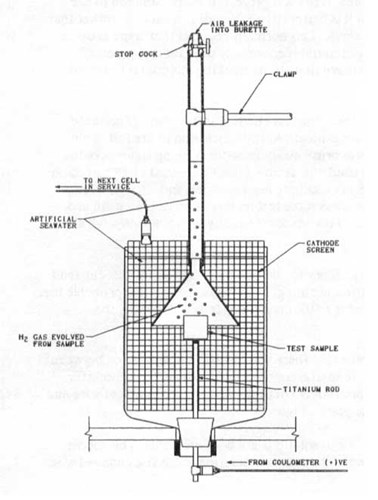
Figure 1 - Hydrogen evolution test set-up
Hydrogen evolution testing - In this method a known current is passed through an anode sample in sea water and collected onto a steel cathode. The hydrogen produced at the anode surface is collected in an inverted burette for a known period of time. Once the volume is collected, the time elapsed and the current passed can be used to calculate the alloy efficiency. In this type of test, the amount of gas collected for unit current and time is inversely proportional to the efficiency of the alloy (i.e. high amount of gas indicates a lower efficiency / capacity). This is a very convenient test because it can be completed in a few days. There are variations on the methodology, depending on the type of anode material being evaluated, but normally the test will be run for six (6) to twenty four (24) hours after an initial anode activation period of twenty four (24) to seventy two (72) hours. The anode will normally be operating at a current density of 4 mA per square inch.
The most common problem encountered with this test method is air leakage into the burette through the stop cock, shown in Figure 1. This will increase the apparent volume of gas collected and give pessimistic results. It is wise to leave burettes filled to the calibration point overnight in a separate container prior to commencing the real tests. This way, any leakage can be detected and the seals can be repaired. Another common problem which bas been noted is that the funnel used to collect the gas from the sample is too close to the cathode screen; this causes gas to be collected from both the anode and cathode reactions. Again, this gives pessimistic results. As a rule of thumb, leave at least two (2) inches between the edge of the collection funnel and the cathode. It is possible to get falsely optimistic results from this test if the collection funnel is too small in relation to the size of the sample. This error essentially allows some of the evolved gas to bypass the measurement system completely.
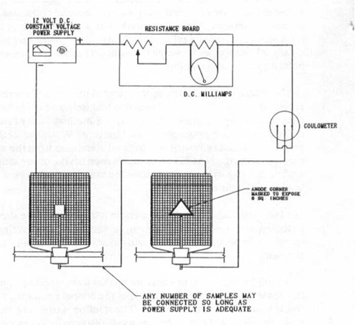
Figure 2 - Typical weight-loss test wiring diagram (can also be used for hydrogen evolution test)
Weight-loss testing - This test is used more and more to determine the capacity of an anode material. The test is generally set up as shown in Figure 2. It is common to run the long-term potential test in conjunction with the weight-loss test, which typically requires 14 days. The NACE test method TMOI90-90 describes a procedure for this test; however, the industry is using a number of variations to this described test method. Below, I will describe some of the problems encountered with this test and some of the solutions that have been successful.
Problem 1: Types of sample - The NACE test method suggests using a one-inch cube as the test piece; it is more common to use either anode corners or cast samples. The general consensus is that it is better to run the tests on "as cast" pieces rather than pieces with machined surfaces; this is particularly true with Indium-activated recipes. Testing "as cast" samples requires that some areas of the sample are masked off before testing. Electro-plater's masking material is commonly used for this process. Clearly it is important to weigh the samples before masking and to ensure that all the masking material is removed before the end-of-test weighing.
Problem 2: Weighing - Clearly, the more material lost for unit current and time, the less efficient the alloy. If accurate results are to be obtained, the cleaning and weighing of the sample are critical. At the conclusion of the test, some testers use a variation on the NACE method. They favor bristle-brush cleaning under running water over the chromium trioxide / phosphoric acid mixture. Whatever method is used, the sample must be cleaned of all corrosion products without removing uncorroded aluminum from the sample. The sample must be dried and allowed to cool before weighing. NACE recommends oven drying of the sample, where as some testers favor an alcohol wash and the sealing the sample in a bag with desiccant until the sample needs to be weighed. This method is OK for some alloys (the ones which tend to oxidize in air).
Problem 3: Inter granular corrosion - Certain alloys tested have shown a tendency to corrode in a non-uniform manner. This can lead to loosely attached metal, which can be easily dislodged during post-test cleaning. If this happens, it is probable that there will be problems with the alloy in any case, but a quick check with a lOX magnifying lens will allow the tester to identify the problem.
Problem 4: Coulometer - On one test set up that was inspected, it was noted that there was insufficient separation between the positive and negative terminals of the copper coulometer. This lead to erroneous results, since the coulometer was bypassed for part of the test. The solution is to install an insulated cover over the positive measurement wire and make the electrical connection at a safe distance from the sacrificial plates. See Figure 3.
Problem 5: Solution maintenance - Errors will develop in the test if the various solutions are not kept fresh. The copper plating solution in the coulometer should be replaced after every test. The sea water solution should be changed when the pH drops below 4.5.

Figure 3 - Copper coulometer detail
Potential testing
The long term potential test (14 days) is normally run in conjunction with the weight-loss test. The only error that can really occur is that the working reference electrode drifts out of calibration. This is easy to monitor if calibration procedures are followed. There will be some variation in the potential depending where the reference electrode is placed, but normally a poor anode will exhibit a potential way below specifications and will be an obvious reject. Such a poor potential would normally be the result of poor chemical composition, and in most cases the heat should have already been rejected.
Summary
There has been a tremendous improvement in anode quality in the last several years, this higher standard in quality will continue to be demanded and enforced as offshore exploration moves into deeper water and offshore repair costs escalate. There is still some work needed on the standardization of electrochemical and chemical testing standards for these anode products.
References
[1] Impressed Current Test Method for Laboratory Testing of Aluminum Anodes - NACE Standard Test Method TMOl90-90
Related Content
Spotlight

Related products & experience


Technical papers


Quality Assurance of Aluminum Sacrificial Anodes for Offshore Applications
by Jim Britton (1993)
ABSTRACT
In recent years there has been a far greater emphasis placed on quality assurance / quality control within the oil and gas industry, this has filtered down to the cathodic protection supply sector within the offshore market. The need for quality aluminum anodes is obvious especially when deep water projects are being considered. This trend toward higher quality control levels has resulted in more third-party inspection work and better defined quality-test procedures [1]. This paper will focus on the practicalities of quality control, and will highlight some of the problems which have been encountered.
Want to receive an email when Deepwater publishes new corrosion-related technical papers, case studies, and more? Sign up for our Corrosion Newsletter using the form below. You can unsubscribe at any time.