Technical Paper
Preventing damage to corrosion protection during pipelaying
by Jim Britton (1996) from Offshore Magazine

Introduction
Corrosion control for offshore pipelines is typically achieved with a combination of pipe coatings supported wilh cathodic protection to cover coating holidays or defects. The nature of offshore pipelines dictates that the most cost effective and reliable method of providing the cathodic protection component is the use of zinc or aluminum alloy bracelet anodes. This method has served the pipeline industry well for many years.
Larger diameter pipelines require a stabilizing weight coating, usually concrete, installed over the thin film corrosion coating. This weight coating provides mechanical protection to the corrosion coating as well as allowing the bracelet anodes to be flush with or even below the outer profile of the pipe. Thus. damage from contact with the pipelay stinger or burial sled to the anodes or coating is minimized.
As the oil and gas industry moves into deeper water, the trend is toward smaller diameter heavy-wall pipe with no weight coating. The smaller the diameter, the greater the risk that an anode can be hooked up on the stinger or in the trenching plow. If an anode is snagged, there is a risk that it will slide along the pipeline and damage the coating or even gouge the pipeline.
Top-mounted anodes
Since most of the possible damage will occur on the pipeline1s journey over the stinger, the anodes have a better survival rate if they are tapered. In that way, they would better traverse the rollers and straighteners on the lay barge.
This anode alteration does not solve the problem entirely, but it does help. Several operators have reduced the risk of a snag by top mounting the anodes on the pipe. Such a position helps passage through the stinger, but would not necessarily help the pipe through a trenching plow or jetting sled.
An additional concern is that the pipe usually will rotate on its axis between the point of exit from the stinger until seabed touchdown. In several documented cases, this rotation has resulted in burial in the mud of all the anodes over a long section of line, leaving the upper half of the pipeline exposed to seawater. The anode's electrical resistance will be significantly increased by this mud bllrial and consequently the current delivered by the anode is reduced.
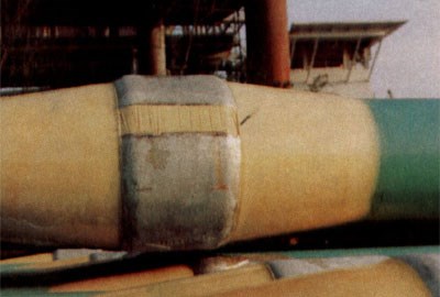
Figure 1 - Polyurethane tapers on each side of the anode bracelets protect the anodes during pipelaying and burial
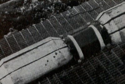
Figure 2 - A top-mounted anode is least vulnerable in the pipelaying process
Current sources
Care must be exercised when specifying these systems to ensure that all possible extraneous sources of electrical current flow in the seawater are appreciated and taken into account. Such sources of current are:
• Poorly or improperly grounded welding
• Generators
• DC powered thrusters
• The cathodic protection system on the barge itself, especially if it is an impressed-current system.
Once these interference sources are quantified, the gradient array can be sized and positioned to do its job accurately. The major advantage of an on-line monitoring system is that problems are detected in real time. With this method, repairs or adjustments can be made during the pipe lay rather than being found during the post-lay inspection, at which time a costly retrofit or repair is the only solution. In summary, the best and most practical measures that can be taken to prevent damage to the corrosion control systems depend on the type of pipeline and the pipelay method. The following general guidelines may prove useful.
• Weight-coated pipelines: Any pipeline with a concrete weight coating should be at low risk provided that the anodes are flush or recessed below the profile of the concrete. No additional precautions are considered useful.
• Reel-laid pipelines: This lay method is particularly suited to deep water, particularly for smaller diameter pipe. Anode tapers would help, but are not always practical given the speed at which the pipe is laid. The pipelines should be designed with top mounted anodes and the probability of mud burial should be reflected in the anode size and spacing. The field gradient monitoring system should be specified because the lines are not weight coated, and anode/coating damage is a real possibility.
• Conventional pipelay (S-Lay) > 200 ft. seawater: Conventionally laid pipe without a weight coating should use square-shouldered anode bracelets with polyurethane anchor tapers. The tapers can be installed in the pipe coating yard before offshore loadout. If the pipe is installed in water depths greater than 200 feet in the Gulf of Mexico, for example, it will not be necessary to bury the line except at safety fairway crossings. Astinger-mounted gradient array should be specified to verify anode attachment and to monitor the condition of the pipe coating. If tapers cannot be installed for any reason, then the anodes should be tapered and the gradient monitoring specified.
• Conventional pipelay (S-Lay) < 200 ft. seawater: Shallow pipe will have to be open trenched or jetted to achieve the required cover. This will involve the use of a towed burial sled or trencher. Under this scenario, the polyurethane anchor tapers with square shouldered anodes offer tremendous benefits due to the enhanced risk of mechanical damage at the burial stage. Similarly, the use of stinger and sled exit point gradient arrays provides absolute verification that no damage is occurring, and if it is, determines the location.
• J-Lay pipelines: This lay method is used only for deep pipelines. Depending on the geometry of the J-Lay frame and the anode installation procedure, there may be minimal risk of damage. Each project should be examined to determine where the last point of mechanical interference with the anode will be.
• Bottom or controlled depth towed pipeline installation: Towed pipelines will have abrasion resistant coatings and may have anodes cast directly onto the pipeline in the foundry. While direct cast anodes can work successfully, they are expensive and not without some problems. Polyurethane anchor tapers will provide the same mechanical stability at a lower cost and allow conventional anodes to be employed. There is no application for on-line monitoring, but a detailed post-lay gradient survey will confirm that no anodes have become dislodged or pipe coating badly damaged.
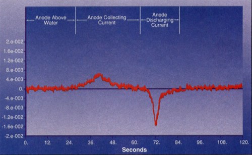
Figure 3 - This printout from an electrode array system positioned on a pipelay vessel stinger indicates the presence of a pipeline anode.
Want to receive an email when Deepwater publishes new corrosion-related technical papers, case studies, and more? Sign up for our Corrosion Newsletter using the form below. You can unsubscribe at any time.
Related content


Technical papers


