Technical Paper
A modern approach to offshore pipeline CP system evaluation
by Jim Britton (2015)


Abstract
With a significant percentage of the offshore pipeline infrastructure exceeding its original design life, the need for life extension is on the increase. These pipelines will need improved surveillance to evaluate the optimum time to repair (retrofit) and to ensure integrity through the extended life cycle.
Introduction
Deepwater leads the industry in innovation in offshore corrosion integrity management and has spent years working on improvements to current technologies to compensate for their shortcomings, improve their accuracy and repeatability, standardize procedures and, above all, provide a significant cost benefit.
The following explains how to get offshore pipeline integrity risks under control and reduce the budget required.
Current practice
Currently, offshore pipeline CP systems are most commonly evaluated using the three electrode survey method as shown in Fig. 1. This method claims to give “close interval” potential data along the pipeline and has been the preferred method since the early 1980s.
The three electrodes are typically referred to as “close”, “field” and “remote”. The method hinges around the ability to make regular stab contacts to the pipeline to establish the “remote” potential of the pipeline at various points. This is usually done by stabbing a bracelet anode and measuring the following values:
V1 – The “close” potential (anode) between the tip and the “close” electrode
V2 – The “remote’ potential between the tip and the “remote” electrode
V3 – The “field,” or electrical field gradient measure, between the “close” electrode and the “field” electrode located on the same probe, usually 20-30 cm away
V4 – The “remote variation” measured between the “close” and “remote” electrodes, which should equal the “remote” minus the “close” potential value.
Armed with this, the ROV can then proceed along the pipeline measuring only V3 and V4, and as long as the close electrode remains close to the pipeline, the potential can be estimated by adjusting the last close reading and adding the variation reading. This can proceed until the next contact calibration point, when the drift in the “remote” potential will be corrected and the data are adjusted to reflect this drift.
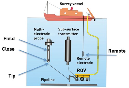
Figure 1 - The three-electrode survey (Courtesy Subspection Ltd)
So, what is wrong with this method?
1. The “close” reference cell must be maintained very close to the pipeline under surveillance, ideally within 50 mm. If this is not maintained, the value of the remote variation reading is diminished to the point of unacceptable inaccuracy.
2. It’s very difficult to do this at all on a buried pipeline, where depth of cover can be from 1-5 meters.
3. In attempting to maintain the electrode position, it is necessary to equip the ROV with wheels that can actually run along the line, or to try to free-fly the line (very difficult to do). In either of these events, the ROV must slow to a survey speed of < 1 Knot, or around 0.3 - 0.5 meters/sec. This means that the cost of the survey is unnecessarily escalated in an attempt to assess the “true” condition of the pipeline.
4. Calibration stabs are required at regular intervals (5 Km is often specified). If this is not done, then the close interval data are being compared to an invalid number. Because it is difficult to get these calibrations on buried lines, they are very often ignored, which makes the surveys worthless for integrity assessment purposes.
5. All “real” potential measurements are usually taken on bracelets, so obviously, the potentials are very negative and unrepresentative of the actual pipeline potential. It is rare to get a real calibration at a cathode (pipeline metal) stab.
6. Because the data are computer generated, there is no real-time assessment available, and post-project reporting can be expensive and time-consuming.
There is now a much better way.
The improved strategy
The improved strategy is a modification for pipelines. To appreciate the elegance of this, it is first necessary to step back and revisit the basic strategy for external corrosion control of offshore pipelines. This is a global strategy that really doesn’t vary in any offshore area, and has been the same since offshore pipelines were first laid in the late 1940s. The corrosion control system on better than 99.5% of offshore pipelines consists of two synergistic elements:
1. A coating system. This is the primary corrosion barrier, usually organic in nature and designed to provide a dielectric barrier that shields the pipeline from corrosive seawater and seabed environments. This coating is usually factory applied to very high standards and is designed to cover up as close to 100% of the steel pipe as feasible. In order for the pipe to be constructed offshore, it is necessary to have field joints where sections of the pipe are welded together in the field. The areas where these welds are to be made are left uncoated in the coating factory and are provided with a compatible “field joint” coating to cover the bare steel before the pipe is lowered to the sea bed.
2. A cathodic protection system. This is designed solely to protect defects in the pipe coating system, and is a key point. The cathodic protection (CP) system may consist of bracelet-type anodes attached at intervals to the pipeline, or there may be discreet anode sled systems. The line may even be short enough to be protected with CP applied at the extremities; in any event its function is the same, to protect defects or deterioration of the pipe coating system that will expose more bare steel to the corrosive environment. It is because of this that the design codes recommend “coating breakdown factors” as percentage coverage loss versus time.
Now that we understand the intended function of the CP system, let’s leverage this to test the resilience of the CP system in routine monitoring; lets test the ability of the CP system to cover a degrading coating system. One way is to remove some coating from the pipeline and verify that the CP system was able to efficiently protect the defect. Of course, this would be counter-productive. But we can introduce a non-critical defect:
Install a “coupon” on the outside of the pipeline with an electrical contact to the pipeline. This coupon would simulate a coating defect and would test the CP system. If the CP system could easily polarize the defect, we would know that there were no other smaller area defects in the region that would not be adequately protected. Moreover, this coupon, if correctly designed, could remain in place and serve as a sample test point for future surveys to give us the pipe (cathode) contact that we really want to see. However, once this coupon were polarized it would behave like any other coating defect on the protected pipeline, but would still represent a worse case scenario, and would reflect other changes in the pipeline’s cathodic protection equilibrium over a large sample area.
We have been asked if it is wise to add these defects to a pipeline, and will they deplete the CP system prematurely? Here is a critical analysis:
Area of a 12” pipeline 10 Km Long = 1017 m2 surface area
Assume each field joint has 10 cm2 bare = 820 joints x 100 (0.82m2 ) = 0.08% bare
Our test cathode coupon is 100 cm2 bare = 0.01 m2 = 9.8x10⁻⁶ % bare
This area would expect to require 600 microamps 0.6 mA of protective current (which would be about 0.5% of the current available from a single bracelet anode). It could hardly be considered a drain on the system, but the fact that it’s a single defect that has been recently placed still gives us the critical information we need.
Such devices are shown in Fig. 2 for bottom-laid pipelines and in Fig. 3 for buried offshore pipelines.
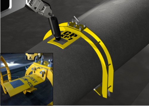
Figure 2 - Retroclamp stab for bottom-laid pipelines
The use of these strategies will allow offshore pipelines to be accurately and repeatably surveyed with a single reading taken at up to 10 Km intervals. Inspection time will be significantly reduced while the data quality and repeatability will improve dramatically. If an ROV only has to approach the pipeline at 10 Km intervals, the survey can be conducted at an elevated height above seabed and survey speeds can be ramped up to 3-4 Knots (1.5 – 2.0 Meters/sec). In real terms, this means that a 50 Km pipeline that would have taken six or seven days can now be easily completed in two or three days.
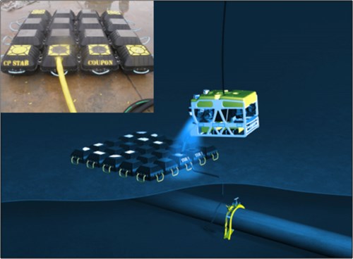
Figure 3 - Clamp and StabMat for buried pipelines
Improved survey equipment
The latest CP survey system has the following key improvements over older, outdated systems.
1. Data redundancy; the new system uses (as do all of our company’s products) dual redundant measurement systems that provide real-time system calibration.
2. As a further redundancy, the actual measured values are displayed in an analog form on the ROV itself (Fig. 4) before being digitized and sent topside to the logging computer. This adds 100% data verification in real time that has been unavailable until now.
3. The basic logging software provided with the equipment is extremely user-friendly and can be supported on any laptop windows computer. It takes only 15 minutes to become proficient.
4. The unit can take power either from the ROV or a subsea battery pack. This provides an option to operate the system with no interface whatsoever to the ROV umbilical system. For localized investigations, this can eliminate expensive interface time, and at all times provides a backup methodology to eliminate offshore downtime in the event of a data transfer error.
5. The EFG probe and the primary contact probe are separate, again, providing redundancy of measurement (Fig. 5).
The equipment is provided with a simple bench tester to quickly verify correct operation and diagnose any problems.
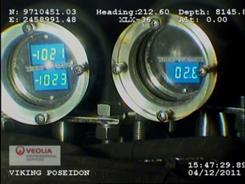
Figure 4 - Analog data display on ROV – Shows real-time calibration and measurement redundancy
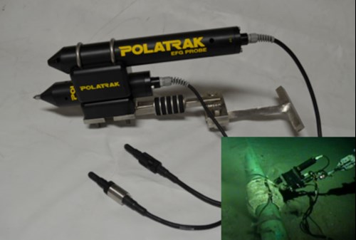
Figure 5 - Analog data display on ROV – Shows real-time calibration and measurement redundancy
Improved data management
Another drawback of current technology is the delay in reporting; in many cases errors are obvious but it’s too late to do anything because the spread has been demobilized. Having reviewed thousands of Km of three-electrode survey data for a wide range of end users, we have noted a multitude of errors and discrepancies. Not one of the reports that we were shown had any correlation of anomaly with a visual image showing the anomaly.
Clearly there was room for improvement, so three years ago we embarked on the development of the RUSS inspection system. RUSS is Real Time Inspection System.
Major improvements are:
1. Reports are generated offshore in real time and can be sent in daily.
2. Each inspection event is stored with a visual; analog and digital data are easily visible and reconcilable. Fig. 6
3. The standard logging software provided with our measurement hardware is compatible with RUSS.
4. The software is compatible with VisualSoft⌘ and most standard video inspection systems ⌘ Product from Forum Energy Technologies
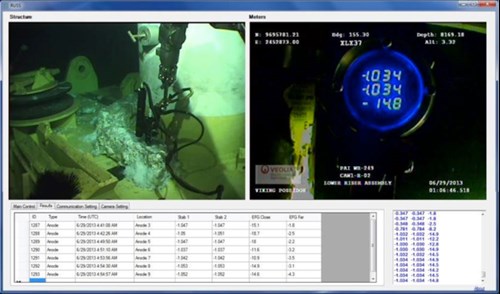
Figure 6 - RUSS Inspection Event – TL (visual record of inspection event) TR (analog data display 2 x potential plus EFG plus ROV status overlay information) BL (event record and data compiler) BR (digital data stream from A-D; last line must match onboard analog values)
With this level of information, data integrity is 100% assured and this simple record generated in real time will form the basis of the final report.
Summary
The preceding describes the methods currently available that can provide an immediate cost benefit and improvement in data confidence. As we get more pipeline mileage instrumented, we will gather important additional data that will facilitate a greater use of computer modeling to be confidently applied to further streamline the integrity management process.
Related Content

Related products & experience


Technical papers


A Modern Approach to Offshore Pipeline CP System Evaluation
by Jim Britton (2015)
ABSTRACT
With a significant percentage of the offshore pipeline infrastructure exceeding its original design life, the need for life extension is on the increase. These pipelines will need improved surveillance to evaluate the optimum time to repair (retrofit) and to ensure integrity through the extended life cycle.