TECHNICAL PAPER
Stray current corrosion during marine welding operations
by Jim Britton (1991) from Materials Performance

Introduction
Instances of “inexplicable” pitting corrosion damage have been observed during routine subsea inspections on offshore platforms – even when the platform cathodic protection system has been working as designed. Evidence suggests that this “corrosion” may have been caused by current discharge from the platform during welding operations. This article describes a solution that has been applied successfully on several projects.
When an offshore platform is installed, the project is divides into several phases. The first phase involves the launch and positioning of the jacket support structure, emerging 10 to 15 ft (3 to 5 m) above the surface. It later supports the deck structure that contains all the various items of specialty equipment. Once the jacket has been positioned, it is secured by pilings driven through the legs or through skirt pile guides into the seabed.
The next two major steps are running the drilling conductors and attaching the prefabricated deck structure to the jacket. These two phases involve a considerable amount of offshore welding, which is conducted with welding generators located on the construction barge and welding leads run over to the platform. The majority of projects use conventional DC welding generators polarized with positive to the welding rod. The electrical resistances between the platform structure and construction barge and the surrounding seawater are extremely low, normally in milliohms. This seawater path offers an attractive circuit for welding currents to flow between the platforms and barge. The magnitude and direction of such current flows directly affect the weight and location of metal loss.
Basic mitigation procedures
Ensure that welding generator cases are grounded to the barge.
• Run individual positive leads from each generator to the platform, ensuring that there is no insulation damage and the leads are not allowed to enter the water.
• Either run the negative return leads to a common insulated bus bar on the barge and run the appropriate number of leads to a common grounding point on the platform, or run individual negative return leads from each generator to the platform, again ensuring that cables have no insulation damage and are not allowed to touch the water.
• Either run the negative return leads to a common insulated buss bar on the barge and run the appropriate number of leads to a common grounding point on the platform, or run individual negative return leads from each generator to the platform, again ensuring that cables have no insulation damage and are not allowed to touch the water.
• Ensure that no fortuitous metallic contacts exist between the platform and the barge.
• Ensure that negative leads are not in any way grounded to the barge unless the positive electrode from the same generator is also being used on the barge.
These procedures are basically those currently specified by the majority of offshore operators.
Inspection problems
The procedures indicated previously certainly reduce risk of serious corrosion damage to a platform. The problem is to verify that true isolation is maintained throughout the project.
A large offshore platform in deep water uses a derrick barge with 20 to 35 welding stations. In addition, there often is a material barge tied alongside carrying conductor piping and pilings.
Problems can arise when welding activity is ongoing on either of the two barges at the same time as welding on the platform. To prevent corrosion of the barge, it is necessary to have both positive and negative leads on the barge. If the positive electrode is then later deployed to work on the platform and the negative ground is overlooked, a stray current situation is set up. It is difficult for an on-site inspector to continuously monitor the status of 20 to 35 pairs of welding leads.
Other common problems are fortuitous electrical paths that may develop between the platform and barge(s). The most common location of such faults is at the catwalk bridge, which is set up to facilitate personnel access between barge and platform. This should be electrically isolated. In rough seas, however, this insulation material can be damaged and fail. Other areas where such problems may arise are steel wire moorings and through crane wire rope systems.
Extent of the problem
The accepted consumption rate of carbon steel under corrosion conditions varies from 17 to 20 Ib/A-y (7.7 to 9.1 x kg/A-y). A large offshore project can use 20- plus welding generators. The normal welding current is 350 to 400 A DC from each. The number of ampere hours of welding activity on a given project varies widely. Assuming the following as an example, we can make general estimates. Assume 20 welding generators working for 10 days at 50 percent utilization; number of ampere hours = 20 x 10 x 12 x 350 or 840,000. At 17 Ib/A-y, the total weight of steel consumed is 1630 lb. This is of course an exaggeration because it assumes that all the current is in fault condition all the time. Even if we consider 10 percent ground fault time, we could expect to lose more than 100 lb of steel.
These problems are never immediately apparent. The welding operations are not affected because the seawater return path is more than adequate to allow the welding currents to flow.
Corrosion sites
It is a common misconception that all the stray current leaves from the anodes on a structure. If this were the case, there would be no significant problem since the previous example results in the loss of only 65 Ib (29 kg) of aluminum. A platform sitting in seawater must be considered as an extremely large number of parallel resistors. The current discharges proportionately from localized sites on the platform depending on local resistance to seawater.
Since the majority of offshore platforms are uncoated, it seems that the current may discharge evenly from the structure. This has not been observed to be the case. A bare steel platform has large areas covered with bonded millscale, areas where the millscale has been removed, and the anode sites. The current preferentially discharges both from areas where millscale has been removed and the anodes. Therefore, the steel areas most prone to corrosion damage are those areas that have been welded, i.e., the joints and nodes. Due to the relative resistance values of the current flow paths, there is little difference between the nodes close to the surface and those deeper on the platform; nor is there any significant different between one side of the platform and another. Therefore, when damage is noted on one node weld, there is a strong probability that it exists on all nodes on the platform. These conclusions have been supported by subsea inspections performed by the writer and from other observations. [1,2]
Consequences
The corrosion damage observed is normally in the form of localized or "shotgun" pitting in the weld bead or the heat-affected zone. Normally, this damage does not threaten the structural integrity of a platform. However, if the cathodic protection system fails or is inadequate, these sites may be subject to additional galvanic corrosion. The presence of this pitting can also hinder routine inspection of the weld.
On an offshore pipeline, the potential for a similar problem is significantly higher. While the number of ampere hours of welding activity per section is reduced, so are the possible sites for stray current discharge. An offshore pipeline always has a coating that should be supplemented with a cathodic protection system. Assuming that the coating is in good condition at installation, the current should discharge from the anode sites. As with a platform, the most likely area for current discharge from the steel lies at the welded joints. This is typically also the weakest link in the integrity of the coating system: the field joints.
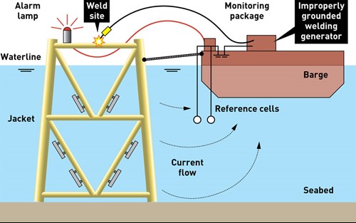
Figure 1 - Schematic system arrangement
Monitoring and control of the problem
Potential measurement
If a stray current situation is active, the most reliable way to detect it involves the measurement of steel to seawater potentials using a voltmeter and a reference electrode. If damage is occurring on the platform, it is essentially acting as an anode to cathodically protect the barge. When this occurs, the potential of the barge is shifted in the negative direction. Therefore, if the barge-to-seawater potential is monitored continuously, the presence of stray currents can be detected. [2]
Other concerns
While this solution may seem simple, there are other problems that must be taken into account before the potential monitoring technique can be effective. First, the barge potential tends to drift with time. The magnitude of these drifts depends on whether or not the barge is cathodically protected and the type of cathodic protection system installed, and the effect of rough seas and stray currents flowing between one barge and another. The use of "spot" potential measurements does not always indicate that a problem exists. Therefore, the potential must be logged on a continual basis, and drifts in the barge potential should be compensated.
If a problem is detected, it must be brought to the attention of the inspector. Any detrimental potential excursions should trigger an alarm. It is necessary to know the extent and duration of the stray current activity responsible. Therefore, the data from the system should be logged for future review. Since this equipment is required to work in a hostile environment, the hardware must be reliable and, wherever possible, backed up. Also, because of the harsh operating environment, the equipment must have a simple-to-operate on-line verification of correct operation of the facility.
Stray current detection and alarm system
This section describes the design, development and operation of a unit that is currently working on a number of offshore platform installation projects in the Gulf of Mexico and the North Sea. The basic system schematic is shown in Figure 1. The equipment is as follows:
Reference electrodes
The first generation of equipment used four silver/silver chloride (Ag/AgCl) reference electrodes, while this system uses only two zinc reference electrodes. The purpose of the reference electrodes is to detect shifts in the barge potential. Originally, it was thought that the high accuracy of Ag/AgCI electrodes was required to detect these shifts. Experience has shown, however, that zinc electrodes offer a better all-around alternative for the following reasons. The actual magnitude of potential shift caused by a stray current varies with the current density that the barge is collecting. In practice, the minimum voltage shift that the system needs to detect is approximately 30 mV on a well-protected barge. These levels are well within the accuracy range of zinc electrodes. Ag/AgCl reference electrodes are not rugged devices. They require a copper cable to transmit their signal back to the control unit. Any flaw in this cable gives an error. Tile potential must be logged on a continual basis, and drifts in the barge potential should be compensated. Ag/AgCI reference electrodes are significantly more expensive than zinc; zinc electrodes are rugged, can be cast on steel conductors and are inexpensive. Use of multiple reference cells was originally specified for two reasons: (1) to provide redundancy, and (2) to monitor more points on the barge to detect the potential swings. Again, experience has shown that if the reference electrode is placed on the same side of the barge as the platform and around 6 to 8 it (2 to 3 m) below the bottom of the barge hull, any potential shifts are detected. This has allowed us to resort to only two cells.
Voltage comparator
The signal from one of the reference electrodes is put onto one side of a voltage comparator. The voltage on the other leg is set via a trim pot to be the natural potential of the barge at time of calibration plus the offset voltage. which causes an alarm (normally 30 to 35 mV). If the signal from the reference electrode equals or exceeds the voltage on the other leg, a signal is sent to a relay, which triggers power to an alarm device. Problems can arise when welding activity is ongoing on either of the two barges at the same time as welding on the platform. The trim pot requires periodic adjustment to reset the alarm threshold against drifting barge potential. This is accomplished by simply reading the actual threshold voltage on a display and trimming the pot to the desired value. This normally can be a daily exercise once the systems have stabilized.
Alarm system
The most effective alarm is a flashing light. The alarm is paralleled to provide a visual indication on the main control unit and on an extension lead to a location that is visible from anywhere on the job site. For convenience, both "test" and "retest" facilities are provided at the control unit and on the remote alarm device. Other controls
For convenience of operation, a number of other facilities are included in the control unit. A voltage meter in combination with a mode selection switch allows the operator to read reference electrode potentials and alarm threshold voltage. The same meter is used when adjusting the alarm threshold. A toggle switch allows selection of either reference electrode as the controlling electrode. Another toggle switch causes the alarm to reset only when manually acknowledged.
Data logger
The unit described previously can work as an on-line detection and alarm system. However, to give the operator a history of the installation, a multichannel data logging system is also provided. In routine application, six channels of data are recorded against real time as follows: Reference Electrode 1 potential, Reference Electrode #2 potential, threshold voltage on comparator, alarm on or off, AC power into unit, and AC power switched on. The combination of these data points allows both an accurate history of the stray current activities and the easy elimination of false alarms. Housing Figure 2 shows the entire field unit with the data logging system installed. It was designed to be a helicopter-transportable item housed in an "off the shelf' plastic waterproof case
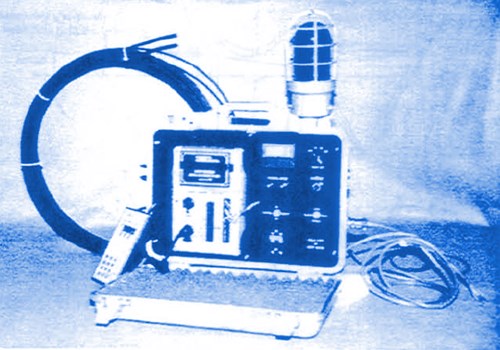
Figure 2 - Field monitoring package
Related content


Technical papers


