TECHNICAL PAPER
Case studies: New concepts in CP systems for brownfield assets
by Jim Britton (2016)

Introduction
As offshore infrastructure ages and the price of oil remains low, the corrosion industry is challenged to find better ways to maintain the integrity of subsea structures. In this context, better means more cost-effective; to develop the most cost-effective system we must approach the problem from the owner’s perspective and ask the right questions. How long does the system have to remain in operation? Are we willing to take on some maintenance work to show an initial cost reduction? Are we willing to consider a shorter life extension and repeat the process when required? Are we willing to change?
Deepwater has pioneered many new methods for offshore cathodic protection life extension over the years, and we have learned quite a few lessons. The following case histories demonstrate not only how different the solutions are, but that they share one thing in common: Each solution is the most appropriate and cost effective for the owner of the asset.
Project case history no. 1
Structure - The structure is a fixed steel drilling / production platform located in 160 meters of water in the northern North Sea [Fig. 1]. The platform was installed in 1980 and was fitted with sacrificial aluminum anodes. The platform is still viable and serves as a critical hub for major fields in the area. Based on this utility, the operator required a 20-year life extension. A survey showed large areas of the structure to be inadequately protected with readings in the range of (-) 0.680 V vs. Ag/AgCl sw. recorded on parts of the structure. It was determined that the large eight-legged structure required a retrofitted cathodic protection current capacity of 7500 Amperes.
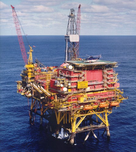
Figure 1 - The North Sea platform is in 160 meters of seawater.
System selection
Project costs in the North Sea are dominated by offshore construction costs, so a solution that minimized boat and ROV time was critical. The system selected was a newly-modified, high-capacity version of a buoyant anode system that has been used on many previous projects. The new anode sleds [Fig. 2] each had a current rating of 950 Amperes. Eight sleds were deployed at various locations on the seabed around the base of the structure, making this the largest-capacity retrofit deployment of ICCP on a single structure. It is worthy of note that the eight installations replaced the 900-plus that would have been required for the sacrificial anode option.
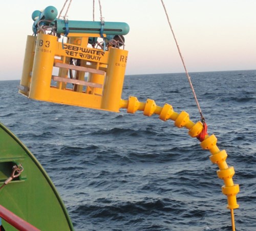
Figure 2 - This is one of eight 950-Ampere ICCP buoyant anode skids that were installed.
Power units
The power units for such an installation require 570 KVA. Normally, we would use outdoor oil-immersed transformer rectifier equipment, but for this current rating, the oil tanks’ size would have been prohibitive because deck space was at a premium. It was decided to use air-cooled thyristor-controlled units housed in ventilated custom-built containers, which minimized the equipment’s footprint. [Fig. 3].
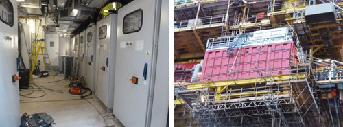
Figure 3 - 570 KVA-rated power units in their custom container; interior view at left, exterior to the right.
Power cables - Routing of the subsea power cables to the anodes is always a challenge. On this particular structure, however, there were two spare J-tubes that could be used after extensive internal cleaning to remove marine fouling accumulations. The cable pulling operation went very smoothly considering that four 1000mm2 cables were pulled into each tube simultaneously. Each of the heavily armored cables had an OD of 70mm.
Modeling and monitoring - In order to predict the current distribution and any possible interference with pipelines, the structure was modeled extensively using BE and FE techniques. The models yielded a diverse set of predicted results, which did not inspire much confidence. It was decided that a monitoring system was required to ensure that the current distribution would be adequate across the large, complex structure. Because of the high costs associated with running cables to multiple locations on the structure, it was decided that a wireless system would be used. Wireless monitors were installed at 12 locations in two vertical rows on either side of the structure [Fig 5]. The bluetooth wireless transceivers were located on ROV-installable clamps. The clamps were fitted with a standard dual-element reference electrode [Fig 6]. The monitoring system can send data unit-to-unit subsea and then transmit through the air-water interface. It is also possible to communicate with the monitors using an ROV. It was necessary to clean heavy marine growth from the structure so the ROV could install the monitors, and this was achieved quickly and efficiently using a brand-new, ROV-mounted flexible cleaning system [Fig 7]. It took just 4 days to install the 12 monitors.
At the time of writing, this system is undergoing commissioning, so no results are available yet on its performance. Results will appear in a later paper that will review a number of our installed systems.
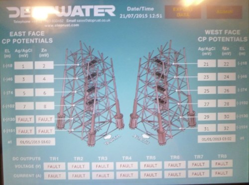
Figure 4 - This monitoring screen shows the location and potentials of the east and west faces of 12 monitors.
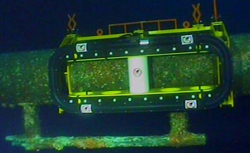
Figure 5 - The ROV-installed wireless monitor is shown; note the depleted original anode at bottom.
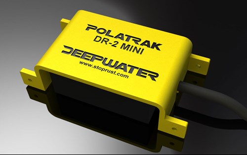
Figure 6 - The dual-element reference electrode (Ag/AgCl & Zinc) used on wireless monitors.
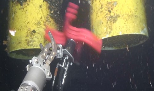
Figure 7 - The ROV FlexiClean™ system shown here reduces cleaning time for subsea installations.
Project history No. 2
The structure
In this case, the structure is a floating offshore storage and offloading installation (FSO) located in the Irish Sea in just 30 meters of water [Fig. 8]. The front of the vessel is connected to a catenary-arm mooring buoy (CALM) that allows 360-degree rotation of the hull (weathervaning). It had a conventional marine ship hull ICCP system that was installed in 1996, began to fail around 2006, and by 2012 was unable to maintain protection. The operator required a life extension until 2028 (15 years). Based on operational records and offshore current requirement testing, it was deemed that 300 Amps of retrofitted cathodic protection capacity would be adequate.
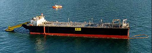
Figure 8 - This FSO in the Irish Sea requires a 15-year life extension.
Options
From the operator perspective, the most important consideration was to avoid any subsea intervention or modification to the hull below the waterline. These constraints left very few options. It was decided that a suspended anode system could be made to work if the following points were considered:
a) The system needed to be engineered to address the obvious potential failure mechanisms, which were fatigue and abrasion.
b) The system would have to be easily recovered. This would allow retrieval ahead of foul weather to protect the anode module and also would allow regular recovery for inspection and maintenance.
These provisions were accepted by the owner and a retrofittable suspended-anode module system was designed. [Fig. 9]
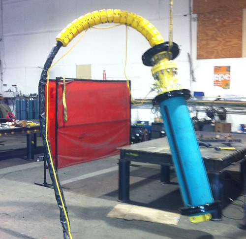
Figure 9 - A suspended anode module was installed using a balcony-mounted deployment and recovery system.
Design considerations
The original design concept used a hang-off frame and a recovery davit [Fig. 10] that were mounted behind the railing on the vessel. This was to simplify installation and allow stowage of the anode module securely on deck in the event that green water conditions prevailed. This was eventually modified by the EPC contractor to a full overboard balcony concept, which uses one for hang-off and one for recovery. [Fig 11]. The anode system is designed to have a current rating of 150 Amperes and is set to hang about 4 meters below the keel of the vessel. The mechanical design of the anode module, power cable system and recovery tethers was highly scrutinized by the certification authorities. The recovery / deployment winch is a simple push button, and redundancy is incorporated wherever possible. Power is automatically cut to the anode as soon as the winch is activated. To track the performance of this new system, a data logger was included to monitor current and potential on the system.
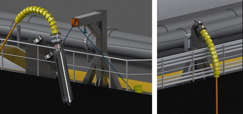
Figure 10 - The original concept would have used an inboard-mounted deploy recovery as shown here.
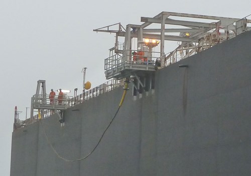
Figure 11 - The system (installed aft) is shown in the recovered position.
Operations
We included the logger mainly to understand the operational profile of such a system. Clearly, the cost advantages of not requiring any subsea intervention were obvious, but we also needed to ensure that the system was functional. What we found out after analysis of the first 15 months of operational data was:
a) The anode system was recovered 23 times, which was an average of once every 20 days. This was more frequent through the winter of 2014.
b) The system was out of the water approximately 30% of the time.
c) Hull potentials were maintained in the protected region for better than 98% of the time and only one region of the hull showed spikes outside protected ranges.
During the first annual inspection visit we found some localized abrasion damage to the tether rope’s outer braiding, which was deemed non critical. We also noted some minor localized abrasion damage to the protective sheath on the power cable that was easily repaired. There was no visible damage to the anode module, which was functioning as designed. One redundant continuity jumper was damaged between a tether clevis and the module frame, which was quickly repaired. As expected, the sacrificial anode protecting the anode module’s steel structure was lightly depleted. Pictures of one of the two modules are shown [Fig 12].
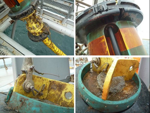
Figure 12 - Photos of the module after 18 months in service shows that it has held up well.
Power units and monitoring
It was hoped that the existing power units could be re-used, but they were not in a suitable state of repair. They were replaced with basic air-cooled potentially-controlled units rated 150A at 24V DC. Control was effected using reference electrodes attached to the anode module’s tether which were compared against the permanent electrodes that were part of the original system. The use of the data loggers allowed us to compensate the IR drop from the reference electrode location to effectively control the system from a semi-remote electrode. This important improvement allows potential control even if the original hull equipment is non-operational, which is usually the case.
The first 18 months of operation showed this concept to be entirely workable and a viable way to address floating systems with a relatively low current requirement. As a large percentage of the FPSO fleet still uses conventional marine ICCP technology, this represents a good option for when those systems inevitably fail in service.
Project case history No. 3
A brownfield fixed platform in 42 meters of water required a short five-year life extension ahead of a decommission decision. The retrofit was completed as part of an IRM program where inspection and repair were conducted on the same mobilization. The platform, a small four-pile wellhead structure, has six wells and is located in the Eugene Island area in the central Gulf of Mexico [Fig. 13]. With all potentials in the range of (-) 0.670 to (-) 0.680 V vs. Ag/AgCl sw, the platform was almost completely depolarized.
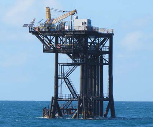
Figure 13 - This wellhead platform in the Gulf of Mexico required a five-year life extension.
The water depth precluded installation of conventional diverless suspended-link anodes [1], so the decision was made to use subsea-installed links [Fig. 14]. The required current was estimated at 175 Amps, so a total of 22 links attached to 11 subsea clamps were ordered. An aluminum weight of 6750 Kg. was calculated to provide the required current for six to seven years.
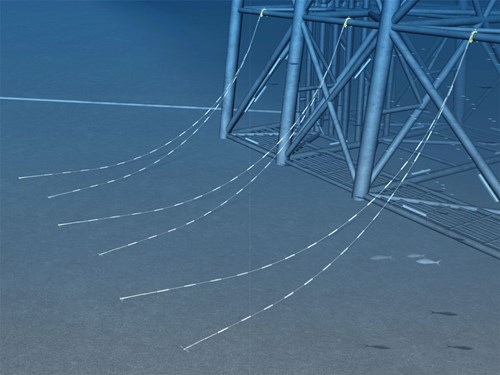
Figure 14 - Link anodes are shown in a "skirt link deployment." They're installed using a shallow air six-man dive crew.
The as-found inspection followed by the repair and the as-left re-inspection took four days offshore using a shallow air six-man dive crew. Some installation images are shown [Fig. 15]. Part of the scope was to record the current output from each anode string after installation so that the customer could optimize similar life extensions on other structures in the fleet. A clamp-on subsea ammeter was used to accomplish this. Some of the results are presented [Fig. 16] and show before-and-after potential measurements and the current output of each string. The current required to protect the structure came in very close to our estimate (160 Amps actual vs. 175 Amps designed).
This method of life extension is very popular in the Gulf of Mexico where there are many old structures requiring only a short life extension. The average life of a “5-Year” system has been shown to be around 6.5 years. Over 600 structures have been fitted with this type of system since 2003.
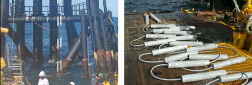
Figure 15 - The skirt link installation and inspections took four days offshore.
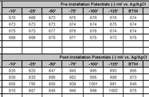
Figure 16 - A portion of data results showing before-and-after potential readings on the platform.
Summary
These three case histories show the diversity of technologies available for the life extension of offshore cathodic protection systems. Other examples are given [2]. It is wise to solicit several options from your solution provider so that the optimal solution can be easily identified.
References
1. RetroLink anode systems http://stoprust.com/products-and-services/retrolink/project case histories.
2. “CP Maintenance For Brownfield Infrastructure” Jim Britton. Presented at Corcon 2012, Goa, India.
Introduction
As offshore infrastructure ages and the price of oil remains low, the corrosion industry is challenged to find better ways to maintain the integrity of subsea structures. In this context, better means more cost-effective; to develop the most cost-effective system we must approach the problem from the owner’s perspective and ask the right questions. How long does the system have to remain in operation? Are we willing to take on some maintenance work to show an initial cost reduction? Are we willing to consider a shorter life extension and repeat the process when required? Are we willing to change?
Deepwater has pioneered many new methods for offshore cathodic protection life extension over the years, and we have learned quite a few lessons. The following case histories demonstrate not only how different the solutions are, but that they share one thing in common: Each solution is the most appropriate and cost effective for the owner of the asset.
PROJECT CASE HISTORY NO. 1
STRUCTURE - The structure is a fixed steel drilling / production platform located in 160 meters of water in the northern North Sea [Fig. 1]. The platform was installed in 1980 and was fitted with sacrificial aluminum anodes. The platform is still viable and serves as a critical hub for major fields in the area. Based on this utility, the operator required a 20-year life extension. A survey showed large areas of the structure to be inadequately protected with readings in the range of (-) 0.680 V vs. Ag/AgCl sw. recorded on parts of the structure. It was determined that the large eight-legged structure required a retrofitted cathodic protection current capacity of 7500 Amperes.
Related Content
Spotlight

Related products & experience


Technical papers


Case studies: New concepts in CP systems for brownfield assets
by Jim Britton (2016)