Technical Paper
Offshore pipeline cathodic protection retrofit strategies
by Jim Britton (2002)

NOTE: This paper was originally written in 2002. Mr. Britton has since written an updated version to address the changes in corrosion control technology for anode replacement that has taken place in the interim. This paper remains in the library for anyone interested in the historical progress of this technology, and namely Deepwater's role in it.
Improvements in Offshore Pipeline Cathodic Protection & Life Extension
Abstract
Many miles of offshore pipelines worldwide are reaching, or have exceeded, the original design life of their cathodic protection systems. Many of these pipelines will be required to function for another 10, 15 or even 20 years. This paper will describe some rational strategies for achieving the desired life extension of the external corrosion control systems at the minimum installed cost. Preliminary surveys, retrofit design methods, installation procedures and hardware, verification and routine post installation inspection methods will be discussed.
Introduction
Information obtained during routine offshore pipeline CP inspections has shown that the CP design criteria used have historically been quite conservative. This is particularly true of pipelines with concrete weight coatings over corrosion coatings. The main reason for this conservatism appears to be in the assumed degradation of the pipeline coating system both initially and over time. The coatings have generally outperformed the design criteria meaning that the anodes have been able to maintain adequate CP levels for much longer than the original design life. A secondary factor appears to be a general overestimation of the current density required to achieve protection. This often results in effective life cycles of cathodic protection systems designed for 20 or 25 years reaching 35 or 40 years.
This is the rule; there are, however, exceptions. Problems have been found on pipelines that become electrically shorted to platforms, pipelines without weight coatings that have had anodes detached during the pipe lay process and pipelines fitted with aluminum anodes of poor quality that have failed to activate. So it could be dangerous to assume the condition of an ageing pipeline if no survey data exist.
Basic anode retrofit strategies
There are three basic strategies that a pipeline owner may adopt, there are a number of theme variations, but in general they are:
The conventional approach - Conduct a detailed survey, analyze the data, plan and schedule the retrofit as needed, execute the retrofit, conduct periodic surveys to verify continued operation of the retrofitted system.
The practical approach - With this approach the owner would reason that the pipeline is already beyond it's original design life, the pipeline needs to remain in service for an extended period of time way beyond even the most conservative estimates of the original CP system’s life expectancy. In this case a retrofit will most probably be required at some point within the next 5 years. So he would adopt the approach of planning a minimal retrofit and at the same time gathering data to assess the condition of the pipeline cathodic protection after the retrofit has been completed.
Retrofit of opportunity - It will become apparent that the majority of the cost of an offshore pipeline retrofit is installation, i.e. the cost of the diving vessel and subsea services, it makes sense to consider planning retrofits in conjunction with other subsea activity on the pipeline. These opportunities present themselves when, for example, a subsea tie-in to an existing pipeline is made. Other similar opportunities exist during routine route inspection, subsea repairs or reburials, or even when a suitable spread is mobilized to the general area to complete other subsea projects. It is a simple matter to ensure that the necessary equipment is available to complete a spot retrofit.
Adopting this strategy, and following an installation procedure that includes monitoring of the anode sled output current as well as “as found” and “as left” pipeline potentials will provide invaluable information on the overall condition of the pipeline CP system in the general area of the retrofit location. These data can be used to eliminate the need for an expensive, detailed pipeline survey while still allowing a safe retrofit system to be engineered for the rest of the pipeline.
Types of retrofit
As with any CP system, three basic options are available, impressed current (ICCP), sacrificial aluminum nodes or hybrid systems. The choice between these systems will be determined largely based on the following broad criteria. Isolation status of the pipeline – If the pipeline is electrically isolated at one or both ends, the application of ICCP will generally be more practical. Practicality of applying ICCP – There are several sub-criteria that will determine the viability of using impressed current as a possible fix, they are:
• Availability of suitable power (AC) supply
• Cost of access and maintenance
• Potential for stray current interference
The length of the pipeline – ICCP can only be deployed at the ends of an offshore pipeline if it starts or terminates at platform or on dry land. The distance that can be protected from an end current source will be limited by the linear resistance of the pipeline and the current required to protect it (coating condition). Generally speaking, ICCP offers no real advantage over sacrificial anodes when considering attenuation.
For short lines (generally less than 5 miles (8 Km.) in length), that run between two platforms or otherwise provide access to a cathodic protection source at either end, the answer may be simply to electrically connect (short) the pipeline to those CP sources at either end. Using attenuation models verified with one time mid point contact potential measurement will usually be sufficient to provide adequate retrofit capacity, at a very attractive price.
Long lines (greater than 10 miles (16 Km.) in length) will invariably require multiple anode sled installations along the pipeline route, the criteria governing the location and frequency of these sleds are discussed later.
Key elements for retrofit projects
Pipeline survey - There are several different survey options that vary from high [1] to low resolution and the selection of the most appropriate method will be determined by the type and accuracy of the data required. Table 1 (below) Compares the merits of the various pre-retrofit survey method options. Obviously the more that is known of the pipeline condition, the more optimization can be put into the retrofit design. This will generally result in a much lower cost installation.
| Survey Method |
Cost | Data Types | Data Accuracy | Generally Applicability |
|---|---|---|---|---|
| 3 Electrode ROV Deployed (Typical Equipment Spread) |
Generally High (3-5K$ / Mile) (1.8 – 3K$ / Km) |
Close Interval Potential & Current Density (EFG) Depth of Burial Temp. / Resistivity GPS (As Built) Visual / Sonar Imaging |
Excellent Very Good Very Good Excellent Excellent Excellent |
Use this for pipelines that are high profile, where long life extension is required and generally on long ageing buried pipelines. |
| 2 Electrode ROV Deployed (Typical Equipment Spread) |
Fairly High 75% - 80% of 3 Electrode Cost |
Close Interval Potential GPS (As Built) Visual / Sonar Imaging |
Excellent Excellent Excellent |
Usually used on exposed pipelines or for post installation baseline surveys. N.R. for buried lines. |
| Lateral Towed Multi-Electrode Survey (Shown Addendum #1) |
Moderate 35% - 45% of 3 Electrode Cost |
Point Potential Point Field Gradient GPS (As Built) |
Good / V Good Good Good / Fair |
Accuracy Improves on un-buried lines. Good for shallow water and beach approaches, also for infield lines. |
| Tow Fish Trailing Wire Surveys |
Moderate 30% - 40% of 3 Electrode Cost |
Close Interval Potential | Poor | Not Recommended in any application |
| Isolated Contact Measurements |
Depends on Number of Points |
Point Potentials Point Depth of Cover |
Excellent Excellent |
Data points are few but reliable, used in conjunction with modeling or to calibrate lateral surveys. |
| End Point Riser Measurement |
Low – fixed price not length dependent |
End Point Riser Potential | Good | Gives same level of useful information as tow fish survey, but gives no real indication of pipeline condition. |
The cost of a typical pipeline retrofit in the Gulf of Mexico will be broken down as follows:
• Design: 2-5%
• Materials: 20-25%
• Installation 75-80%
Thus it follows that optimization of the installation should receive the most attention. This can be achieved by knowing the following things about the pipeline:
• CP System & Coating Condition – This determines the number of sled sites required.
• Depth of Cover – On a buried line this is critical to minimize or eliminate excavations.
• Pipeline Location (XY) – Time wasted locating the pipeline is expensive.
The key is to safely protect the pipeline with the minimum number of locations. Top level survey intelligence can be an enormous help in this endeavor, but the economics should be closely evaluated before reaching a decision to survey.
Design - When setting about designing a retrofit for an offshore pipeline, there are a number of key elements that drive the design approach. I am not going to go into great length about design criteria such as current density requirements etc. these are well appreciated by corrosion engineers in the field. But the following points of knowledge control the design:
• Coating Condition
• Pipe Wall Thickness
• Existing Anode Condition
• General Potential Levels on Pipeline
• Isolated or Shorted at End Points
• Extent of Burial
• Operating Temperature
• Water Depth
• Location of Other Pipelines / Tie-Ins etc.
Each of the pods was designed to supplement the current required for two wellhead / riser assemblies for 10 years design life. An ROV support vessel successfully deployed the pods, and the tie backs made with the ROV. A post-installation survey showed that potentials had been shifted negatively on all risers, indicating that the TSA was no longer the primary source of CP.
In our field experience it is possible to space anode retrofit sleds as far as 10-12000 feet and achieve adequate cathodic protection overlap Table 3 (below). Shows data obtained while retrofitting an offshore pipeline in the Gulf of Mexico, the installation sites 1 – 14 are approximately 12000 feet apart and were installed in number order over a seven day time period. The numbers clearly show overlap to each successive site. This on a pipeline reaching the end of its original CP design life but still maintaining cathodic protection levels in the potential range of (-) 0.880 V vs. Ag/AgCl sw. or more negative.
| Loc. No. | Pre | Post | Shift | Current |
|---|---|---|---|---|
| 1 | 0.880 | 1.016 | 0.136 | 4.050 |
| 2 | 0.933 | 1.027 | 0.094 | N-R |
| 3 | 0.941 | 1.011 | 0.070 | 3.340 |
| 4 | 0.990 | 1.026 | 0.036 | 2.350 |
| 5 | 0.937 | 1.006 | 0.069 | 0.420 |
| 6 | 0.914 | 0.987 | 0.073 | 3.830 |
| 7 | 0.931 | 0.995 | 0.064 | 3.050 |
| 8 | 0.938 | 1.000 | 0.062 | 2.840 |
| 9 | 0.931 | 0.999 | 0.068 | 2.410 |
| 10 | 0.955 | 0.998 | 0.043 | 1.210 |
| 11 | 0.990 | 1.026 | 0.036 | 1.980 |
| 12 | 0.968 | 0.990 | 0.022 | 0.710 |
| 13 | 0.968 | 0.990 | 0.022 | 1.000 |
| 14 | 0.970 | 0.997 | 0.027 | 1.700 |
| Pre and Post are potentials measured on pipe before and after attachment of retrofit sled. Shift is simply the change in potential. Current is the sled current output in amps shortly after connection. All potentials are (-) Volts vs. Ag/AgCl sw. Reference. |
||||
Installation planning - Several key factors come into play when planning the installation of an offshore pipeline cathodic protection retrofit:
Installation spread requirement – This is the offshore support equipment required to complete the job. The equipment required will generally be determined by pipeline location, length, water depth and depth of burial. A pipeline that runs from on offshore facility to an onshore destination may require two completely different equipment spreads to complete the project. The locally available equipment will also drive the decision in many areas of the world.
In the Gulf of Mexico, North Sea and other major offshore areas there is a usually a wide range of equipment for hire. So if we decide to use a Remotely Operated Vehicle (ROV) spread only, do we need a Dynamically Positioned (DP) support vessel or a Four Point Anchor Vessel (FPV). DP can command a day rate double that of an equivalently sized and otherwise similarly equipped FPV. With an average anchor deploy / recover time of around 6-8 hours per location the DP can complete well over twice as many installations as the FPV under certain conditions, but the bottom time required at each location has to be relatively short with respect to anchor handling time .. these among several other considerations make for a complex analysis. The wrong call could cost somebody hundreds of thousands of dollars on even a modest sized retrofit program.
Hardware requirements - When designing pipeline retrofit hardware, there are some key requirements over and above providing the correct design from a CP standpoint (which goes somewhat without saying). The equipment must provide the following, and will not look the same for every project:
1. Ease of safe handling offshore, correct lift points, know weight limits of installation equipment on site, etc.
2. Provide quick installation for Diver/ROV, minimize time on bottom.
3. Allow positive verification of performance upon installation, preferably by current output rather than potential measurement alone.
4. Be environmentally friendly, no net snag points, toxic materials of construction etc.
The hardware consists generally of three main elements:
1. Anode sled(s) - Anode sleds may be galvanic or impressed current. Figure. 1 shows a typical galvanic mud sled designed to operate below the seabed. This sled has an anode weight of 1250 Net lb (568 Kg). of Al-Zn-In anodes. These sleds are generally deployed at a short distance from the pipeline (10 – 15 feet 3 to 4.5 m). Impressed current sleds will take several forms depending on location, but will generally have to be located a little further away from the pipeline to be fully effective.
Sacrificial anode sleds are usually equipped with a cable-shunt type current measuring facility (Figure. 2). This allows surface or subsea readout of anode sled current output. It is a good idea to provide some magnetic or sonar reflectors that will enable ease of relocation with low cost towed survey apparatus, they can also be useful for calibration of smart pigs.
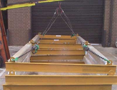
Figure 1 - ROV utilizing SunStation's light-powered readout
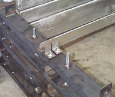
Figure 2 - ROV utilizing SunStation's light-powered readout
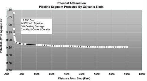
Figure 3 - Potential attenuation prediction
Note that discreet anode sleds have a finite resistance, this can be seen in the typical attenuation predictive output (shown Figure. 3). The large voltage drop at the sled location is caused by this resistance. This is not present when zero resistance end current sources or potentially controlled impressed current sources are used. Shorting a pipeline to a platform would represent a zero resistance current source.
2. Interconnect cables - These are the cables that connect the anode to the pipeline, so they have to be designed to perform long term. Fortunately they are generally very corrosion resistant and being on the cathodic half of the circuit receive the benefit of full time cathodic protection. It is sound practice to include a wire rope strain relief to eliminate the possibility of excess strain at the connection terminals. Dual redundant cables should always be provided as a minimum, cross sectional area will typically need to be in the 2/0 to 4/0 AWG range. Multi-strand locomotive style cable is preferred over stranded conductor constructions.
Remember that the equipment is only 20% of the project cost. Don’t cut corners that could compromise performance.
3. Attachment to pipeline - The pipeline attachment is possibly the most critical element. Mechanical connections are the most cost effective, and also the speediest to install. A new design of attachment clamp that has been successfully used on a number of projects is shown in Figure. 4. The clamp has the benefit of installing over weight coatings, and without the need to fully excavate the pipeline, its “breakaway system” eliminates potential damage from snagging. These features alone can save several hours of bottom time per location, more if the pipeline is deeply covered. The clamp has been successfully installed both by divers and ROV. The constant torque features and material selections ensure the long term integrity of the electro-mechanical connection.
Other attachment methods to be considered include friction welding, hyperbaeric or wetwelding, but the circumstances would have to be unusual to justify the significant cost penalties associated with these methods.
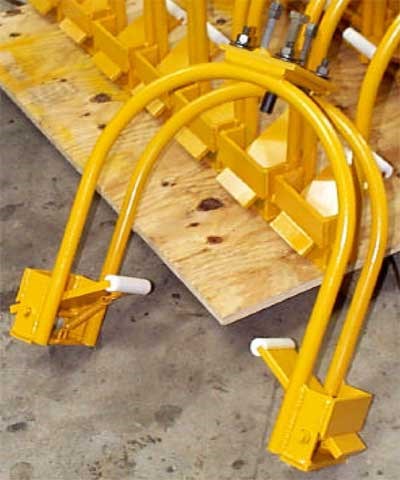
Figure 4 - Quick-Fit pipeline attachment clamp
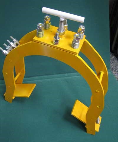
Figure 5 - 2006 remodel of the same clamp (Called RetroClamp)
Installation - The installation should proceed well if properly planned, a key element is to have a corrosion specialist available to make and interpret the various measurements taken at each location. In this way critical field adjustments can be made if the recorded data are not meeting or exceeding predicted levels.
It is also key to have a qualified survey company on board to accurately spot the position of each retrofit site. This will be critical to long-term re-survey strategy.
Verification and monitoring - There are two phases of verification and monitoring; Short term and long term, in the short term it is important to verify the retrofitted system performance. This stage of monitoring comprises of the following basic measurement types:
• Pre and post-installation pipeline potentials.
• Early polarization curves (sled current plotted against change in pipeline potential over a short period after grounding of the anode sled).
These data, when evaluated on the pipeline as a whole, provide a wealth of "real" CP performance information that can be used to optimize asset life cycle inspection and mechanical integrity management costs. It is these life cycle inspection requirements that make up the long term monitoring. The data obtained during installation can now be put to use to plan periodic system operational verification. The large evenly distributed CP current sources are now the virtual “offshore test stations” that need simply be scanned with a low cost towed apparatus [2], to verify proper system function.
This level of CP system performance verification, is higher than that available o probably 90% plus of offshore pipelines. Deepwater pipelines are increasingly being protected by a few isolated sled current sources, this will eventually change the way in which offshore pipelines are monitored.
It seems more than reasonable to suggest that certain aspects of this technology approach may be applicable to new pipelines in even moderate water depths. Pipeline monitoring is much harder to do on buried offshore pipelines, the larger signal strengths from the distributed sleds can be more easily detected and verified on buried pipelines, than those from small bracelets with low level field gradients.
Summary and conclusions
When considering an offshore pipeline retrofit remember the following key points to ensure the best result.
1) There are no two offshore pipelines that are the same in every aspect. Evaluate the options carefully before finalizing a retrofit strategy, understand where things can go wrong.
2) Don’t base a decision on bad or uncertain survey information.
3) Work with subsea experts to determine most appropriate installation scenario for the pipeline.
4) Plan the retrofit to allow simple, low cost life cycle monitoring.
5) Work with other groups within the company to make best use of all pipeline access opportunities, have anode sleds available to send offshore at short notice, always carry a tip contact type CP probe to get potential readings.
6) Never go offshore without a corrosion expert.
I hope that this short paper has given the reader some food for thought.
References
1. NACE Corrosion 92 Paper No. 422 Britton J. N. “Continuous Surveys of Offshore Cathodic Protection System Performance on Buried Pipelines in The Gulf of Mexico”
2. “Offshore Pipeline Cathodic Protection Surveys – A Technology Update” Presented at New Orleans Section Meeting – October 2001. Copy available from Deepwater.
Addendum 1 - Lateral towed survey system
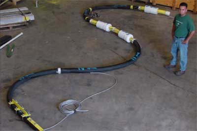
Figure 6
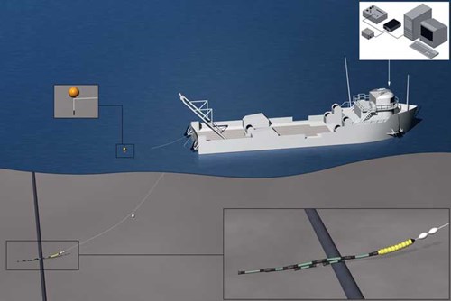
Figure 7
Want to receive an email when Deepwater publishes new corrosion-related technical papers, case studies, and more? Sign up for our Corrosion Newsletter using the form below. You can unsubscribe at any time.
Related content


Technical papers


