Riser base CP modeling
Used modeling to determine remaining life
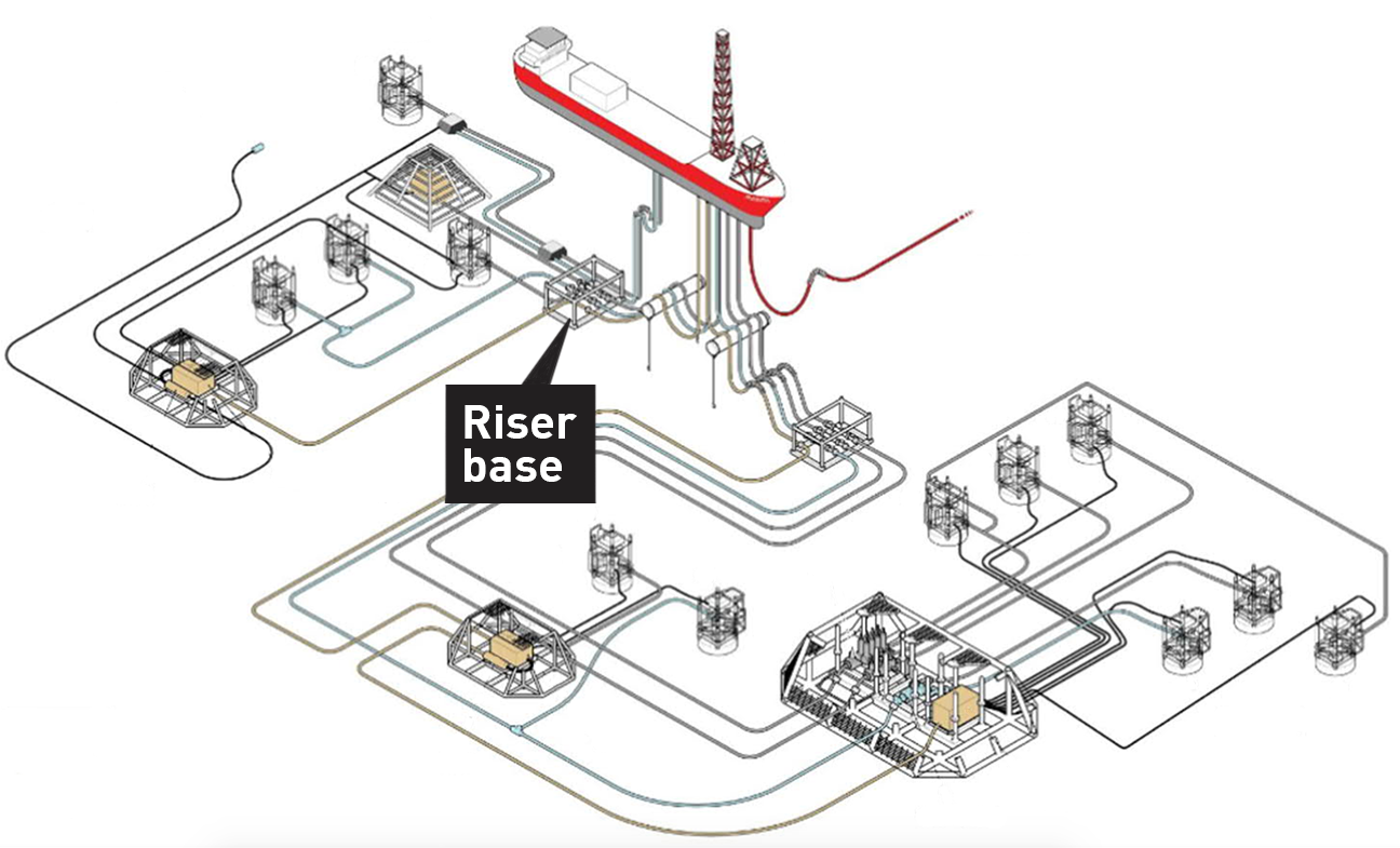
CP modeling used to verify 15-year life extension on riser base
Simulation for a life extension of 15 years on a riser base using North Sea conditions
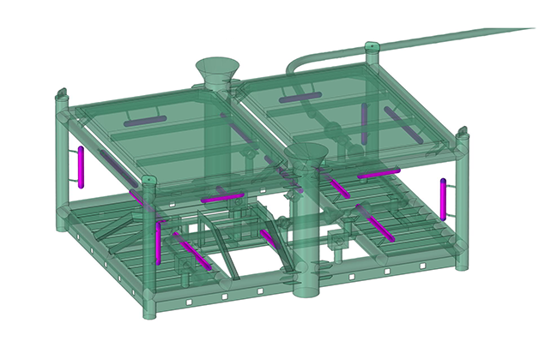
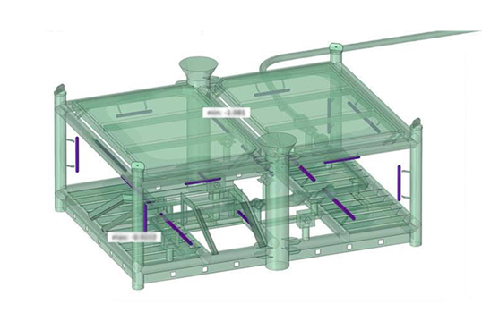
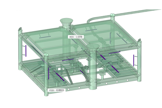
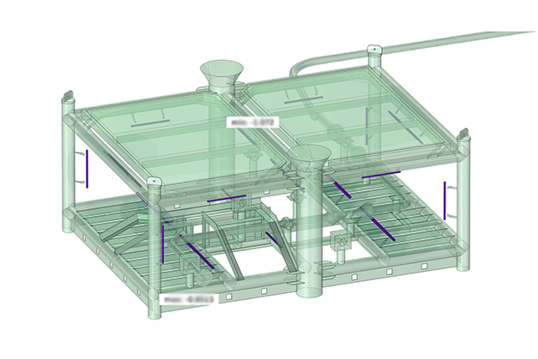
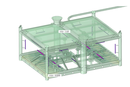
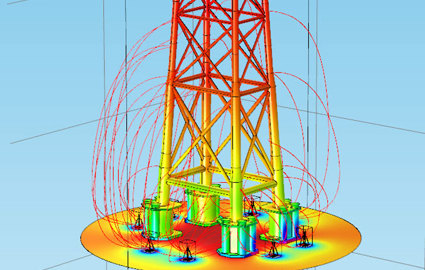
Deepwater modeled cathodic protection (CP) of a riser base with 3D to determine whether a CP retrofit was needed. This result was compared to a traditional CP assessment (no modeling) on an identical structure conducted less than a year previously. That report recommended a retrofit of both riser bases using two RetroPod™ anode sleds; the other riser base was retrofit as recommended, and its historical and pre/post install CP survey was used as a check against the new CP design simulation in the model.
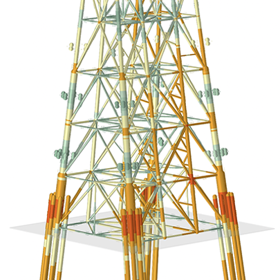
The model geometry was built in 3D CAD software based on data files and structural drawings already in existence. Additional asset and environmental information were incorporated into the model parameters.
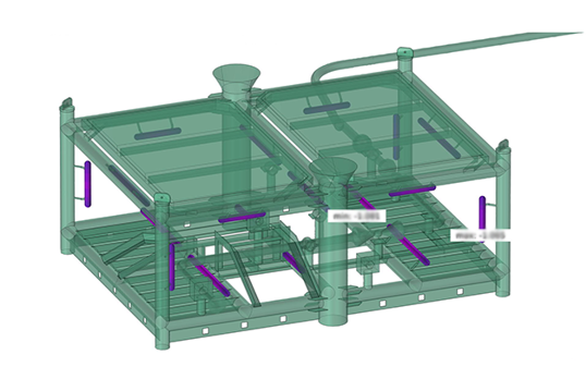
The time-resolved model was evaluated from asset installation through full depolarization. From this baseline, model calibration was performed by optimizing parameters related to coating breakdown and sacrificial anode performance to accurately reflect the historical CP survey data.
The calibrated model provides a predictive timeline of depolarization and was used to identify the possibility of unprotected steel potentials in limited areas of the riser base within the next year, requiring a retrofit to avoid possible corrosion. Scenarios of various sled location and quantity around the riser base was simulated to validate the prior design and investigate if fewer sleds could be used given the newly-calibrated model.
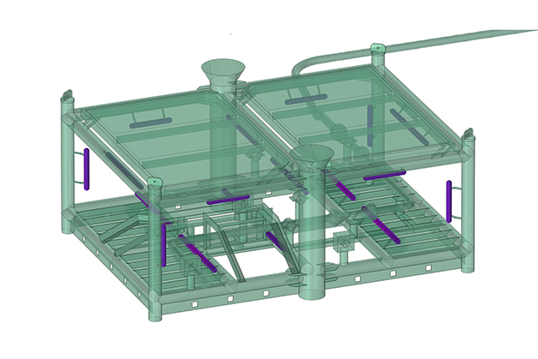
Modeling showed that installing one RetroPod™ would result in a rapid potential shift of up to 60 mV. The structure then depolarizes, with the first possible corrosion occurring in about two years. While some parts of the asset remain protected, the majority of the asset would be unprotected within four years.
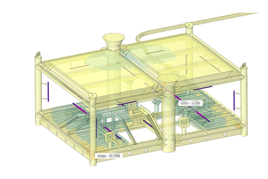
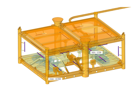
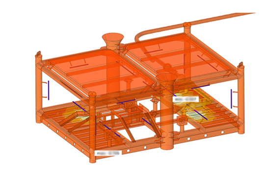
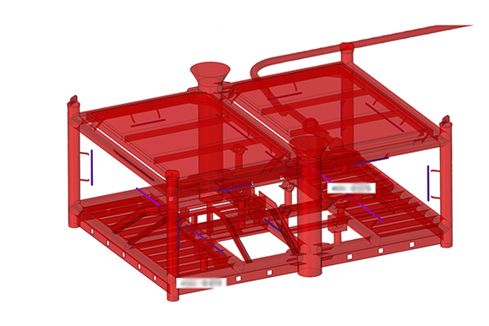
Two-and-three-pod cases revealed that the internal cathode geometry was important in this case, whereby steel internal to the structure (which cannot be easily surveyed with a contact probe) was the site of the earliest depolarization.
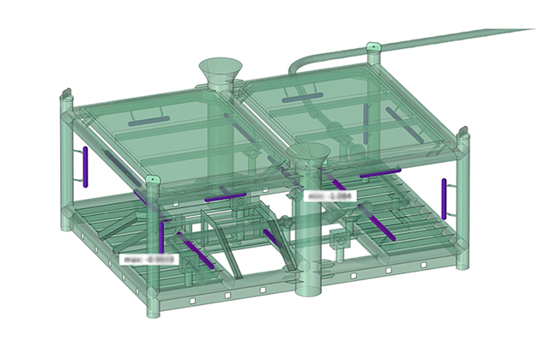
Relocating the pods much closer to the asset yielded a meaningful improvement in retrofit performance but would require work-class ROV operations in very tight quarters. An alternative strategy was developed, where a platform-sized anode would be installed on each of the two large pile-guide funnels and secured with integrated beam clamps. Placing the two additional anodes directly on the structure appears to be less risky than moving the pods significantly closer and maintains polarization on all surfaces through the life-extension target.
Recommendations:
An installation of two RetroPods™ with the addition of two pile-guide anodes would ensure full protection for the entire asset during the life extension.
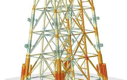
As-built anode output model progression (from new to depleted)
