Technical article
SunStation™ - New solar-powered CP tool helps reduce corrosion risks
by Brian Gibbs

Read article on Offshore-Mag.com
The increasing demands on subsea infrastructure to work at greater depths, in harsher conditions, and for longer design lives requires a new look at the tools and techniques used for cathodic protection (CP) monitoring. This is increasingly important in today’s world, where regulatory oversight and the need to effectively manage risks is paramount.

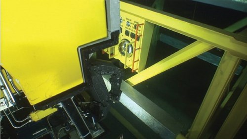
Figure 1 - ROV utilizing SunStation's light-powered readout
Introduction
The conventional way of verifying that a CP system is working effectively is to measure the electrochemical potential, referred to commonly as CP readings. This technology was developed for use on shallow-water fixed platforms and other large structures, such as ship hulls, where the technology works well. Complex subsea equipment presents major challenges for gathering good CP data when using the tools developed for large simple structures. Yes, CP readings are recorded, but their value can be limited if they are not taken consistently and at the locations where the corrosion risk is greatest. The consequence of poor data can result in additional inspections, premature retrofit of anodes, or unexpected failure.
Permanently installed monitoring tools have been in use for decades and generally these require cables to be brought up above water to electrically powered meters. This approach is totally impractical for remote deepwater infrastructure. Deepwater Corrosion Services has addressed this impediment by incorporating solar panels into the CP monitoring system. This new product – the SunStation – is a solar-powered monitoring tool that has many advantages over the traditional, and often difficult, approach to taking contact probe CP readings.
The illumination provided by the ROV lights is sufficient to activate the solar panels. This compact, stand-alone monitoring system requires only the ROV’s lights and video camera to gather the vital CP data from the strategically positioned CP measurement probes.
This solution to CP monitoring provides the operator and the regulatory bodies with consistent and reliable data, which is vital for an effective risk mitigation plan. Additionally, it reduces ROV operational time and, therefore, operating costs. The technical advantages, the reliability of the data, and the reduced operational cost by far outweighs the cost of supplying and installing the monitoring system.
The goal here is to show how bad corrosion data hampers the ability of the integrity engineer to offer sound judgement on the condition of the subsea infrastructure, and how new technology can help mitigate this risk.
Managing risk?
The key to successful integrity management is to demonstrate that risks are managed to acceptably low levels. Key corrosion data provides this assurance. For the integrity management authority, the challenge is dealing with the uncertainty of verifying that the materials of fabrication are performing well over the expected service life; often, even longer because of the need to continue extending the operating life of fields.
In complex subsea equipment, we mix a variety of metals to meet specific design and operating needs. We often build increasingly complex systems, many of which need protection from the natural process of corrosion. In doing so, we mix corrosion resistant alloys and a range of carbon steels, with the possible addition of other materials such as titanium. These materials are electrochemically incompatible, meaning that one metal will cause another to corrode. While this approach creates an effective mechanical design, it presents challenges from an integrity management standpoint.
Carbon steels require CP to limit the effects of seawater corrosion. The effective solution to address the corrosion issues and electrochemical imbalance is, and probably will always be, sacrificial anodes. This generates two main challenges for the designer: where to attach the anodes, and how to monitor their effectiveness.
Attachment of the anode is usually confined to structural components, such as the frames, and the design relies on a series of mechanical (bolted) connections to create the electrical continuity required for the anodes to protect safety-critical components.
In deepwater environments, verifying the ongoing in-service effectiveness of CP comes down to two simple techniques. The first is visual inspection to see that the anodes are present, functioning, and to look for signs of corrosion. The second is CP measurement, which typically employs a simple probe that contacts steel somewhere on the perimeter of the equipment.
This simple CP measurement probe, intended for checking CP on offshore structures, only tests the location where the measurement is made. It does not examine the safety-critical (usually pressure containing) components, and it can be concluded that taking CP measurements at non-critical locations does not provide the sound data needed to verify that corrosion risks are being well managed.
Enhanced measurement
The primary purpose of CP inspection is to confirm that the metals at risk of corrosion are protected by cathodic protection at the time of inspection. The secondary purpose is to predict whether the CP system will continue to perform adequately for some period (the next three to five years, for example), or when retrofit would be necessary for continued service.
Good data is essential to making this judgement. The classic approach to CP inspections is to take measurements on accessible parts of the exterior envelope. This is of limited value, however. These test points are typically on secondary items, such as structural frames and not on, or even near, the safety critical components. This happens because of limited ROV dexterity in these complex and confined spaces on subsea equipment.

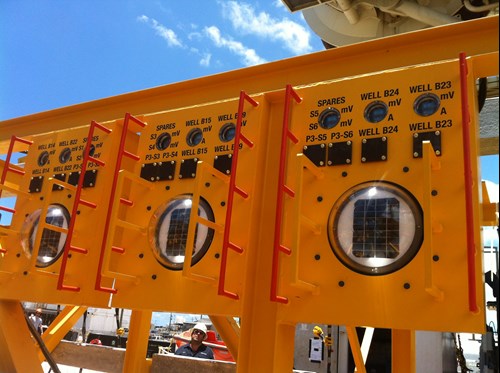
Figure 2 - Solar-powered test panels mounted on subsea equipment

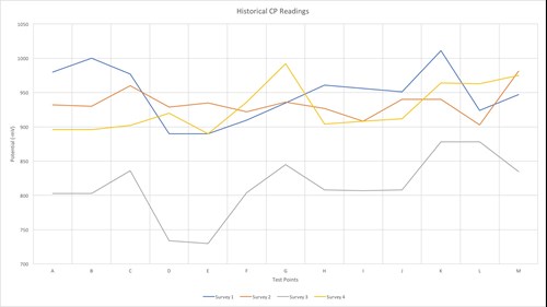
Figure 3 - Historical CP readings
So, what is good data? The best way to answer this question is to first consider what the typical trend of CP measurements should be; then, compare this to real data. For a sacrificial CP system, when taking measurements with a silver/silver-chloride reference cell, the timeline is something like this:
• The instant the equipment is submerged, the bare metals are unprotected. The CP readings of bare carbon steel would typically be -600mV to -650mV.
• As the CP electrochemical process occurs, the CP readings move toward the protected range, which is more negative than -800mV.
• In time, perhaps a month or more from immersion, the CP reading becomes reasonably static. A well protected structure would have a CP value around -950mV.
• This CP level remains reasonable stable over the bulk of the life of the anodes - typically 15 to 20 years. There will be minor changes, around +/- 25mV, caused by several factors that include reading inaccuracies. These minor fluctuations are not serious and are to be expected.
• As the anodes reach the end of their lives, they put out less current and, consequently, the CP levels reduce exponentially.
• As a rule of thumb, retrofit CP is needed once the CP level drops to -850mV. The objective is to replace the anodes before the item becomes unprotected.
In summary, the data graph should show an initial rapid increase in CP level, followed by a prolonged period of slightly fluctuating readings, and ending with a decay curve that leads to under and then no protection.
Now, when one looks at some real-life data, there can be challenges. A set of readings taken on an item of subsea equipment using an ROV fitted with an industry standard contact CP probe illustrates the potential challenges. The problems included the following:
• At any given test point, the year-on-year data varied wildly – much more than the generally acceptable +/-25mV fluctuation. The lines of data should lie on top of each other, within a +/-25mV fluctuation, or show a progressive decay from inspection to inspection point.
• It is permissible to have variations in CP from place to place on one entity. CP is never totally uniform. If the variations are true changes in CP, they should be reasonably consistent year on year.
• One dataset dropped dramatically and indicated under protection at multiple points. Then, another dataset jumped back to the general range of earlier sets. It is all too easy to say that one set is the bad apple, but there’s no way of knowing for sure without another inspection.
It is very likely that the inspections were performed by different crews and ROVs. They may not have had the previous inspection results available, leaving them without a reference point. In the ideal world, this is not relevant. Good operators with good equipment should achieve good data. The problem is that there are many factors, beyond the scope of this article, that justify the data.
The main point is that data like this does not conclusively prove that the corrosion risks are being well managed, and there must be a better way of monitoring the CP status of critical and expensive subsea infrastructure as part of a risk management plan.
Permanent CP monitoring
Permanently installed CP monitoring is not new. As early as 1972, there have been permanent monitoring systems in offshore platforms. Deepwater Corrosion Services has been involved in providing monitoring equipment since the mid-1980s, with permanently installed zinc reference electrodes on Gulf of Mexico structures. These older systems only worked on fixed or floating structures, as monitoring was done topsides.
Since then, the company has developed a vast improvement to this early technology with the solar-powered monitoring system that allows for consistent and reliable measurements at the locations where integrity risks are their greatest. The system only requires the ROV’s lights and camera to take the measurements. This system has been successfully installed at various locations, including Shell’s Olympus field in the Gulf of Mexico.
Solar-powered system
The fully self-contained monitoring system consists of two primary elements: the reference electrodes and the test panels.
The reference electrodes are zinc because of their stability and proven longevity. These are installed at points on the equipment/structure where corrosion risks are at their greatest.
The test panels are fixed to the structure at locations accessible to the ROV. They contain voltmeters, powered by the photocells, to measure the CP potentials. In the event of electrical/electronic failure, the test panel has stab plates where the ROV can take conventional probe readings.
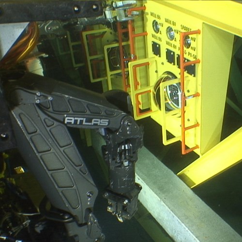
Once installed, taking readings is straightforward. As the ROV approaches the test panel, its lights activate the solar panels under the glass domes. The power generated brings the voltmeter and ammeter to life. The CP potential and current are displayed on the gauges at the top of the panel, which is captured by the ROV camera. In addition to the consistency and repeatability of readings, this is a fast scan system that significantly reduces ROV work time.
The benefits of the system seem to be self-evident. Even so, there appears to be a need for a paradigm shift in the offshore industry before this technology is widely accepted.

Figure 5 - ROV interrogating SunStation™