Technical Paper
Offshore cathodic protection surveys must cover all pipeline facilities
by Jim Britton (1999) from Offshore Pipeline Technology magazine
Introduction
The homogeneous nature of the subsea environment helps make corrosion control systems more reliable than those onshore.
With the Gulf of Mexico's pipeline infrastructure getting older, it makes sense to conduct a detailed, effective cathodic-protection (CP) survey of the entire system before external corrosion can start taking place. Almost 6,000 miles of active pipelines in the Gulf of Mexico are more than 20 years old, and another 1,200 miles are over 30 years old. Many of these aging systems are transmission lines, which are needed to transport oil and gas from new leases in deep-water locations.
Historically, offshore pipeline CP surveys have consisted of measuring the potential of the riser at each end of the system at least once a year. This obviously does not provide information on the condition of the pipeline between those risers. Offshore pipeline cathodic protection systems are inherently more reliable than systems on onshore lines. The galvanic aluminum or zinc anode bracelets normally used in conjunction with high-performance pipe coatings provide reliable external corrosion control for the pipeline's life. There are exceptions, and these exceptions are the ones that could result in an external corrosion failure.
The homogeneous nature of the offshore environment helps make corrosion control more predictable. However, the entire pipeline will degrade at the same rate if the CP system has depleted. This means that the first external corrosion hole probably signals the end of the useful life of the pipeline, because there will be hundreds of other sites that are close to perforation.
In-line inspection
Smart pigs are used to a limited degree on offshore pipelines, and high-resolution tools are capable of detecting pipe-wall loss through corrosion. They also are able to differentiate between internal or external corrosion. They are not capable of evaluating the remaining life of the anodes on the outside of the line. Unless in-line inspections are run regularly, they are of little use in a corrosion maintenance and integrity program.
A pipeline showing no external corrosion could have a CP system that is in the last stages of depolarization, and active corrosion cells could be initiating even as the tool is in the line. Given the corrosion rate of steel in seawater, it won't take long for wall loss to become evident. The line could fail in three or four years.
It should be noted that the in-line inspection companies are not running these tools for free. A routine in-line inspection program could represent a significant hump in the maintenance budget. A detailed CP survey will yield predictive information that can satisfy the operator that the CP system will remain in place for many years to come. Conversely, the operator had better start thinking retrofit if the line has remaining service requirements.
Post lay inspection
New pipelines in the Gulf of Mexico are inspected with divers or a remotely operated vehicle (ROV) after installation. This inspection verifies the line is adequately buried, if required. Also, it will verify that the line doesn't have any unsupported spans.
If a CP survey system were integrated with this survey, the correct operation of the CP system and the coating condition could be verified beyond any doubt. This would eliminate the need for additional inspections for the next 20 years unless there was a mechanical incident of some kind.
The incremental cost of adding this service is minimal: $200-$300/mi.** To go back and survey the line later would cost $2,500-$3,OOO/mi.** It is completely beyond comprehension why the Gulf of Mexico is one of the few offshore producing areas where this practice is not standard.
Types of survey
Trailing wire surveys (tow fish surveys)
This survey was the earliest attempt to conduct close interval surveys on offshore lines. Why not? It was the way in which onshore lines were surveyed. Well, there are a number of fundamental reasons why the method is flawed. During an onshore close-interval survey, the standard practice is to locate the pipeline and set flags in the ground every 100 feet or so. The reason for this is so the reference electrode can be positioned exactly over the pipeline. Every so often, there also will be a test station consisting of a wire attached to the pipeline and brought above ground. At each test station, the wire is reconnected and the IR error in the pipe line is corrected. Because the pipe is buried several feet below the ground, it is necessary to correct the IR error caused by the CP current flow in the soil. Thus, the CP current is interrupted and the readings recorded with the "off" cycle.
Offshore practitioners of this type survey do none of this. The practice is to simply hook a wire to the riser at one end of the pipeline and head off in the general direction of the pipeline in a zigzag fashion with a reference electrode hanging from the boat on a long wire. (Fig. I) There is absolutely zero value in this type survey other than to determine the remote potential of the riser.
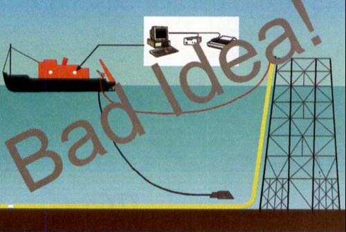
Figure 1 - Illustrations show trailing wire survey technique
A quick look at any charts produced by this method usually will show a sharp gradient at the start of the run. This is followed by miles of flat-line data with the occasional ripple; no spikes at anodes, no depressions at major tie-ins, just useless flat-line information which has nothing whatsoever to do with the potential of the pipeline. Again, it boggles the mind why the only place in the world that still considers using this survey is the Gulf of Mexico. Mexico's corrosion communities long ago realized the errors in this approach. They have been using valid survey techniques in the Gulf of Campeche for almost a decade. Problems now are being found that went completely undetected when the trailing wire system was the standard.
Multiple electrode surveys
The multiple electrode survey approach was originally conceived in the late '70s in the North Sea when the need for accurate survey data became apparent. A schematic layout of a three-electrode survey system is shown in Fig. 2. The basic theory is as follows: the remote cell, attached to the ROV cage or tether or suspended from the survey vessel, is maintained at all times remote from the pipeline. The remote potential doesn't vary more than a couple of millivolts per mile. Essentially, it is a flat line as demonstrated by the trailing-wire method.
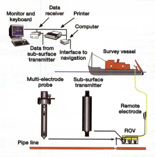
Figure 2 - Schematic layout of three electrode system.
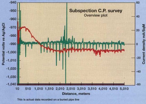
Figure 3 - Graph showing three-electrode survey plot
It is this level of information that is required to truly diagnose the condition of a pipeline's CP and coating system. A comparison of trailing wire data and multiple electrode data is shown in Fig. 4.
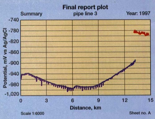
Figure 4 - Three electrode versus trailing wire data with end of trailing wire data coming from right and main plot showing stab verified three electrode data
Combined surveys
The previously referenced mobilization costs and equipment day rate will decrease with greater equipment utilization. If an ROV spread is needed to do a job, see if the CP survey can be cost-effectively combined. In this way, the actual cost of gathering the CP information is reduced by an order of magnitude.
Standard risk-based inspection strategy works well to develop a survey program. This usually results in a minimal amount of annual survey for any given operator, with significantly improved peace of mind that the pipeline's CP system is preserving the integrity of the asset.
** Price estimates represent conditions during this article's year of publication.
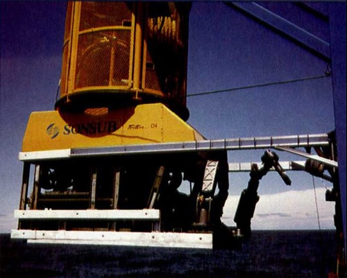
Figure 5 - Work class ROV set up for pipeline survey with pipe tracker on front and multi-electrode CP probe in manipulator arm.
Want to receive an email when Deepwater publishes new corrosion-related technical papers, case studies, and more? Sign up for our Corrosion Newsletter using the form below. You can unsubscribe at any time.
Related Content
Offshore cathodic protection surveys must cover all pipeline facilities
by Jim Britton (1999) from Offshore Pipeline Technology magazine
Introduction
The homogeneous nature of the subsea environment helps make corrosion control systems more reliable than those onshore.
With the Gulf of Mexico's pipeline infrastructure getting older, it makes sense to conduct a detailed, effective cathodic-protection (CP) survey of the entire system before external corrosion can start taking place. Almost 6,000 miles of active pipelines in the Gulf of Mexico are more than 20 years old, and another 1,200 miles are over 30 years old. Many of these aging systems are transmission lines, which are needed to transport oil and gas from new leases in deep-water locations.
Historically, offshore pipeline CP surveys have consisted of measuring the potential of the riser at each end of the system at least once a year. This obviously does not provide information on the condition of the pipeline between those risers. Offshore pipeline cathodic protection systems are inherently more reliable than systems on onshore lines. The galvanic aluminum or zinc anode bracelets usually used in conjunction with high-performance pipe coatings, provide reliable external corrosion control for the pipeline's life. There are exceptions, and these exceptions are the ones that could result in an external corrosion failure.
The homogeneous nature of the offshore environment helps make corrosion control more predictable. However, the entire pipeline will degrade at the same rate if the CP system has depleted. This means that the first external corrosion hole probably signals the end of the useful life of the pipeline, because there will be hundreds of other sites that are close to perforation.
In-line inspection
Smart pigs are used to a limited degree on offshore pipelines, and high-resolution tools are capable of detecting pipe-wall loss through corrosion. They also are able to differentiate between internal or external corrosion. They are not capable of evaluating the remaining life of the anodes on the outside of the line. Unless in-line inspections are run regularly, they are of little use in a corrosion maintenance and integrity program.
A pipe line showing no external corrosion could have a CP system that is in the last stages of depolarization, and active corrosion cells could be initiating even as the tool is in the line. Given the corrosion rate of steel in seawater, it won't take long for wall loss to become evident. The line could fail in three or four years.
It should be noted that the in-line inspection companies are not running these tools for free. A routine in-line inspection program could represent a significant hump in the maintenance budget. A detailed CP survey will yield predictive information that can satisfy the operator that the CP system will remain in place for many years to come. Conversely, the operator had better start thinking retrofit if the line has remaining service requirements.
Post lay inspection
New pipelines in the Gulf of Mexico are inspected with divers or a remotely operated vehicle (ROV) after installation. This inspection verifies the line is adequately buried, if required. Also, it will verify that the line doesn't have any unsupported spans.
If a CP survey system were integrated with this survey, the correct operation of the CP system and the coating condition could be verified beyond any doubt. This would eliminate the need for additional inspections for the next 20 years unless there was a mechanical incident of some kind.
The incremental cost of adding this service is minimal: $200-$300/mi.** To go back and survey the line later would cost $2,500-$3,OOO/mi.** It is completely beyond comprehension why the Gulf of Mexico is one of the few offshore producing areas where this practice is not standard.
Types of survey
Trailing wire surveys (tow fish surveys)
This survey was the earliest attempt to conduct close interval surveys on offshore lines. Why not? It was the way in which onshore lines were surveyed. Well, there are a number of fundamental reasons why the method is flawed. During an onshore close-interval survey, the standard practice is to locate the pipeline and set flags in the ground every 100 feet or so. The reason for this is so the reference electrode can be positioned exactly over the pipeline. Every so often, there also will be a test station consisting of a wire attached to the pipeline and brought above ground. At each test station, the wire is reconnected and the IR error in the pipe line is corrected. Because the pipe is buried several feet below the ground, it is necessary to correct the IR error caused by the CP current flow in the soil. Thus, the CP current is interrupted and the readings recorded with the "off" cycle.
Offshore practitioners of this type survey do none of this. The practice is to simply hook a wire to the riser at one end of the pipeline and head off in the general direction of the pipeline in a zigzag fashion with a reference electrode hanging from the boat on a long wire. (Fig. I) There is absolutely zero value in this type survey other than to determine the remote potential of the riser.
A quick look at any charts produced by this method usually will show a sharp gradient at the start of the run. This is followed by miles of flat-line data with the occasional ripple; no spikes at anodes, no depressions at major tie-ins, just useless flat-line information which has nothing whatsoever to do with the potential of the pipeline. Again, it boggles the mind why the only place in the world that still considers using this survey is the Gulf of Mexico. Mexico's corrosion communities long ago realized the errors in this approach. They have been using valid survey techniques in the Gulf of Campeche for almost a decade. Problems now are being found that went completely undetected when the trailing wire system was the standard.
Multiple electrode surveys
The multiple electrode survey approach was originally conceived in the late '70s in the North Sea when the need for accurate survey data became apparent. A schematic layout of a three-electrode survey system is shown in Fig. 2. The basic theory is as follows: the remote cell, attached to the ROV cage or tether or suspended from the survey vessel, is maintained at all times remote from the pipeline. The remote potential doesn't vary more than a couple of millivolts per mile. Essentially, it is a flat line as demonstrated by the trailing-wire method.
This remote electrode is compared to a close electrode, which is maintained in as close proximity to the pipeline as possible. This electrode is mounted in the ROV manipulator, or may be carried by the diver. Any local changes in the pipeline potential create a gradient between the close and remote electrodes, and the magnitude and polarity of this variation reflect electrochemical events occurring at the pipeline. If the close electrode passes an anode – which hopefully is discharging current – then a sharp negative variation will be noted. A large coating defect hopefully would be collecting current and would show up as a positive spike. The chart in Fig. 3 shows data from a typical three-electrode survey. The red line is the potential trace. Periodic hard contacts with anodes every 4 or 5 miles on the line are required to re-calibrate remote potential and to verify actual pipeline potential. Variations are added to the actual potential to give the true pipeline value. The third electrode is positioned at a known fixed distance from the close electrode and is compared to the close electrode to give a field gradient value close to the pipeline.
This field gradient is used to compute the surface current density on the line. The current density profile (green trace in Fig. 3), is invaluable in determining the condition of the pipe line's CP system. The busy area near the center of the trace in Fig. 3 shows an area of coating damage (upward green spikes) and shows increased current density at the anodes (downward green spikes). Observation of the red trace in this area would barely show this damage, because the CP system is doing its job in maintaining the pipeline at a protected level. But the anodes in this area will consume far more quickly than other anodes on the line. The start of the line shows a couple of anodes working hard. This is because the riser is shorted to the platform. Also of interest is the fact that some anodes have ceased to function (missing downward green spikes), and have already been consumed.
Developing survey strategy
Obviously, it would make sense to check cathodic protection levels on all new pipe lines during the post lay inspection, then forget about them, unless problems are found. For existing lines, it would make sense to rank them by age. The cost of performing a detailed close interval survey is quite high, as previously indicated. This is due to the array of sophisticated equipment which must be assembled to perform such a survey. A standard work-class ROV equipped to survey a buried pipeline is shown in Fig. 5. Using a dynamically-positioned vessel is optimal, although any supply boat can be used providing it has lateral thrusters.
The ROV should be a work class vehicle ideally, although smaller 25-hp vehicles have been used successfully. An active pipe tracking system is needed, as well as a GPS positioning system and ROV tracking system. All this in addition to the normal survey equipment. So, spread cost is around $25,000 to $30,000 for a 24-hr capability. Mobilization cost for such a spread usually is around $50,000** in the Gulf of Mexico. Strategies employing consortiums will become more popular because of the shared costs, better equipment utilization and improved equipment reliability that leads to higher survey efficiency.
Combined surveys
The previously referenced mobilization costs and equipment day rate will come down with greater equipment utilization. If an ROV spread is needed to do a job, see if the CP survey can be cost effectively combined. In this way the actual cost of gathering the CP information is reduced by an order of magnitude.
Standard risk-based inspection strategy works well to develop a survey program. This usually results in a minimal amount of annual survey for any given operator, with significantly improved peace of mind that the pipeline's CP system is preserving the integrity of the asset.
** Price estimates represent conditions during this article's year of publication.