Technical Paper
External corrosion control and inspection of deep water pipelines
by Jim Britton (2001)

Introduction
The external corrosion control of offshore pipelines has, for many years, been accomplished with pipe coatings supplemented with galvanic cathodic protection in the form of zinc or aluminum anode bracelets. This basic methodology works equally well in deep water as it does in shallow. There are however some very important differences in the way corrosion control systems operate in deep water versus shallow water. There are also other obvious differences in the way the pipelines are built and installed that have an effect on the corrosion control strategy, it is these differences which will be addressed.
The deep water environment
To understand how corrosion mechanisms vary in deep water, it is necessary to appreciate how the deepwater environment differs from the shallow water areas. There is a common misconception that steel does not corrode in very deep water. "Look at the Titanic, the darn thing's as good as new and its been down there for a hundred years." We have all heard this at some time. In truth, the Titanic is a crumbling wreck and corrosion will eventually destroy every trace of the vessel. The initial attack is at galvanic couples, just as it would be on an unprotected pipeline. It is true that the corrosion rate is less in deep water, but it is far from being zero.
Temperature - As water depth increases, temperature decreases and this decrease in temperature affects the ability of calcareous deposits to form. Calcareous deposits are the result of the cathodic protection polarization process. These deposits are critical in the cathodic protection process as they act like crude coating systems to reduce the current required from the anodes, making it possible to provide cathodic protection for very long life with relatively small anodes. At low temperature the deposits form much more slowly, and when formed, are generally less dense than deposits formed under equivalent conditions in shallow water. This slowed formation requires higher levels of cathodic protection current to sustain anti-corrosion protection (maintenance current density), and thus more anodes are needed.
Conductivity - The electrical conductivity of seawater increases as temperature increases, so at depth the conductivity is lower. This means that the amount of cathodic protection current which could be expected from a conventional anode will be much lower in deep water than in shallow water. So we have a dilemma; more current is required, less is available and so we need more anodes, or anodes of a different shape.
Pipe coatings - As previously mentioned, coatings are the primary external corrosion defense. Coatings operate by simply providing an oxygen diffusion barrier between the steel and the seawater, so coatings reduce the surface area of exposed steel by better than 90%. From the previous paragraph, the importance of coatings in deep water can be appreciated. The majority of new pipelines are protected with fusion bonded epoxy coating (FBE). These pipeline coatings perform equally well in deep or shallow water but are subject to mechanical damage during the pipe lay operation. When formulating a corrosion-control design, it will be necessary to assign a coating breakdown factor, which should be done wisely. None of the design guidelines gives a good recommendation for a number to use, and the most appropriate number will vary depending on the type of coating and the pipeline installation method. A safe number to use is 2-3% initial coating damage and 5% at the end of 20 years; beyond this it would be wise to allow an additional 1% / year final breakdown. This is a pessimistic number. Pipeline survey results on old lines have typically shown that the coatings hold up very well and the supplemental cathodic protection seems to enhance the long-term integrity of the coatings by eliminating corrosion undercutting.
Thermal sprayed coatings - The use of sprayed metallic coatings (Aluminum and Zinc) has been gaining popularity in submerged offshore applications, including some pipelines. This coating offers the benefits of low cost with excellent corrosion protection over a wide range of temperature and conditions. While TS coatings do provide a measure of cathodic protection, they still require supplemental anodes but the quantity can be significantly reduced. These coatings are still under development for broad-based pipeline applications, but expect to see continued progress.
Cathodic protection - As previously discussed, cathodic protection requirements do vary from shallow to deep water. The following points must be borne in mind when designing a cathodic protection system for a deep-water pipeline.
Anode chemistry - Historically, zinc was the material of choice for pipelines offshore. The material was cheap, easy to cast, and because of its relatively low melting point, was also easy to alloy. The material is also able to operate in either sea water or seabed sediments. Some operators still favor zinc. In the mid seventies, the use of indium-activated aluminum anodes became the norm. The aluminum anodes were lighter, operated more efficiently and were also able to work in seabed sediments. The use of aluminum on platforms was also on the riser mainly due to weight saving, and thus the high demand for aluminum anodes made the price very competitive. The use of aluminum activated with indium carried into the deep-water market again because of price and weight. In the early 90s, some activation problems were observed on these anodes operating in cold water (+/- 4°C), and it was found that adjusting the chemistry to tighten the ranges of critical elements eliminated the problem. The adjusted chemistry being widely used in the Gulf of Mexico is shown below (Table 1).
Table 1
Anode chemistry modification for cold water service
| Element | Typical composition | Cold water composition |
|---|---|---|
| Iron (Fe) | 0.10% max | 0.07% max |
| Zinc (Zn) | 2.8 – 7.0% | 4.75 - 5.25% |
| Copper (Cu) | 0.006% max | 0.005% max |
| Silicon (Si) | 0.20% max | 0.10% max |
| Indium (In) | 0.01 – 0.03% | 0.015% - 0.025% |
| Cadmium (Cd) | Not Specified | 0.002% max |
| Others (each) | 0.02% max | 0.02% max |
| Aluminum (Al) | Remainder | Remainder |
Anode inspection - We have established the fact that anode chemistry is critical. When procuring anodes it is critical to ensure that the anodes are electrochemically tested at the anticipated service temperature, not ambient seawater. It is also important to monitor the chemical composition of the anodes carefully. To assist in this endeavor, a qualified inspector should be used to monitor the anode production. EXPECT what you INSPECT. NACE International has an excellent guideline document on electrochemical testing of anodes, TM190-98.
Current density - The amount of cathodic protection current required to achieve optimal polarization (minimize maintenance current), varies depending on the environment. It takes a lot less current to get the job done if the pipe is buried, but the lower conductivity of the seabed sediments versus the seawater means that the anodes cannot deliver as much current. The recommended current density for shallow-water pipelines in the Gulf of Mexico is 2 mA/ft2 in the mud and 5 mA/ft2 in the water (maintenance current densities). We recommend the following design approach for deep-water pipelines. Continue to use 2 mA/ft2 in the mud zone but increase to 7mA/ft2 in the water zone. In addition, ensure that the design will still be correct if an anode is detached from the pipe; this means that the spacing should be closer than normal. In most conditions, anodes on deepwater pipelines should not exceed 250 feet spacing.
Pipeline installation - It is important to recognize that damage can occur during pipeline installation [1]. Anodes may be detached through mechanical contact with the pipe lay equipment or coatings may be damaged. On projects employing the reel-lay method, it is not uncommon to attach both halves of the anode bracelet on the top half of the pipe (Figure 1), this minimizes the potential for damage from the stinger. Beware that the pipe may rotate 180° placing ALL the anode material in the mud, this unlikely scenario should be reflected in the design. The use of cast-in-place polyurethane tapers is not uncommon for pipe lay situations where the anodes can be pre-installed. The tapers provide a smooth transition and also anchor the anode grounding wire in place.
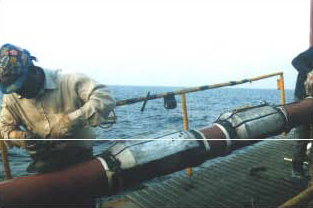
Figure 1 - Anodes on top of pipe on reel lay barge
Electrical isolation - The question of electrical isolation has long been a subject of debate among offshore pipeliners. Taken from the corrosion control perspective, we always recommend isolation of pipelines under the following circumstances:
1. The pipeline is connected to a bare steel structure (i.e. a platform).
2. The pipeline is connected to any structure of foreign ownership.
3. A new pipeline is tied into an old pipeline.
4. The pipeline is to be cathodically protected with impressed current.
5. The pipeline is operating at elevated temperature.
6. The pipeline is made of a corrosion-resistant alloy (CRA).
Remember that it is much easier to electrically short a pipeline than to electrically isolate it when in service. Having the pipeline isolated also gives far more options for troubleshooting and monitoring over the life of the equipment.
Inspection
Introduction - This paper will only discuss the inspection of the external corrosion control system on deep water pipelines; It will not address the other inspection methods for sand monitoring and internal corrosion. Some smart pigs are able to detect external corrosion pitting. This is usually too late, as the goal of monitoring is to stop corrosion, not to find it once it has already happened!
New pipelines - When planning a new pipeline, there are many things that can and should be done up front to ensure that the corrosion control system will work trouble-free over the life cycle of the pipeline. Starting with good specification writing and vendor qualification, it includes plant inspection of coatings and cathodic protection materials. A critical phase is the installation; inspection on the pipe lay vessel is the last chance to catch problems before they become major problems. The use of stinger-mounted sensors [1] to detect anode detachment of coating damage should be considered. These electrochemical sensors give instant indication of a problem which can usually be remedied just as quickly so that expensive retrofits can be avoided [2]. The most important inspection is the post lay. It's usually performed by an ROV to verify that here are no spans or other anomalies and is the perfect opportunity to verify the operational status of the cathodic protection and coating system. If this survey proves that all the anodes are attached, activated and adequately protecting the pipe, and that the coating system has not sustained serious damage, then it will not normally be necessary to re-survey the line for over 10 years. This is by far the most cost effective survey that can be performed because the incremental cost addition to the post-lay survey is usually less than $300.00 / mile equivalent (cost relevant only at the time of this paper).
Existing pipelines - Existing pipelines can be surveyed with ROV-mounted survey systems, and high and low resolution systems are available. The decision to use high or low resolution will depend upon the level of information required. High-resolution systems will give not only accurate potential profiles of the line but also current density, which is particularly important if a remaining life estimate is required. A typical high-resolution survey plot is shown in Figure 2. An ROV equipped with high-resolution survey equipment is shown in Figure 3. Low-resolution systems give only potential profiles. These are usually sufficient for post-lay inspections. Note that any survey of a pipeline cathodic protection system which utilizes a trailing ground wire will be erroneous, and could give dangerously optimistic (or pessimistic) results.
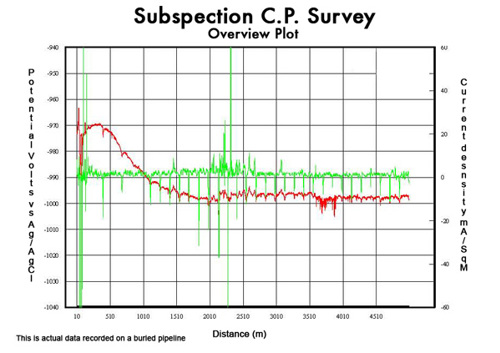
Figure 2 - Three electrode survey plot. Red trace (Potential), Green (Current density)
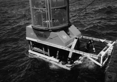
Figure 3 - Work class ROV with survey equipment - CP system and pipe tracker (circa 2001).
New equipment has recently become available for cathodic protection monitoring on deep water equipment. A self-contained 10,000 ft rated CP measuring system (Figure 3) requires no ROV interface. This system is useful for checking a few isolated points on a pipeline with minimum operational hassle. This system (called Deep C Meter) is ideal for checking subsea insulators, short flow line jumpers and anode bracelets.
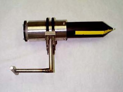
Figure 4 - Self-contained deep water CP probe
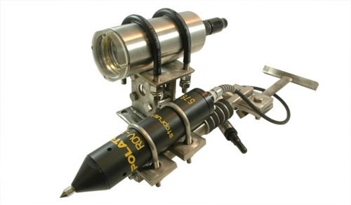
Figure 5 - Updated model of this probe - Deep C Meter
Summary
The cost of providing cathodic protection to a deep-water pipeline is typically less than 1% of the project cost. It makes no sense to compromise the long-term integrity of a pipeline by under-designing the cathodic protection system. Expect to see continued improvement and development in the area of thermally sprayed aluminum and zinc coatings, and a greater use of ROV-integrated inspection systems.
References
1. Offshore Magazine - April 1996 - J. Britton "Protecting Pipeline Corrosion Control Systems During Installation"
2. CORROSION 97 - Paper 470 R. Winters and A. Holk "Cathodic Protection Retrofit of an Offshore Pipeline"
Want to receive an email when Deepwater publishes new corrosion-related technical papers, case studies, and more? Sign up for our Corrosion Newsletter using the form below. You can unsubscribe at any time.
Related content


Technical papers


