Technical Paper
Recent advances in offshore cathodic protection monitoring
by Jim Britton, John P. LaFontaine and Grant T. Gibson (2000)
Abstract
Offshore production facilities and pipelines are being installed in new, more hostile environments. Advances in Cathodic Protection Monitoring for new structure types in deepwater as well as for high temperatures are discussed. New portable ROV instrumentation as well as permanent monitoring of parameters affecting cathodic protection system performance are reviewed.
Introduction
The factors driving the use and design of cathodic protection (CP) monitoring equipment have not changed since first use, however our understanding of the process of cathodic protection has. And so has information technology. Recently proposed new design approaches (1), have increased the importance of area-specific steady-state polarization data. More complex monitoring systems are being deployed to generate these data. Improvements in remote data transmission have revolutionized collection of and access to the information, thus making it more available to the right people. Today, structures in deep water are engineered to the highest standards, leaving little room for error in the corrosion protection systems. Corrosion resistant and high-strength materials used are often susceptible to damage if exposed to cathodic protection, magnifying the need for accurate, real time monitoring. Ongoing improvements in remotely operated vehicle (ROV) technology affects the way cathodic protection systems are being monitored and maintained, and how information is gathered and transmitted. Finally the need to understand how temperature and water velocity affect cathodic protection design is challenging the imagination of monitoring system designers.
Application of new design methodology
The slope parameter cathodic protection design method will no doubt replace or at least enhance the design of many sea-water immersed cathodic protection systems in the future. The method requires an understanding of the polarization curve of the construction material in a particular oceanographic environment. Variation of the curve shape with current density, sea-water flow rate, temperature and resistivity are not accurately known for all values measurable in sea-water. The best way to obtain these curves is to monitor actual installations and develop real polarization curves for a particular area. Thus the use of shunted current density sensors (Figure 1) and anode current monitors (Figure 2) is growing in popularity. The parameters measured from these instruments offer obvious benefits. First, the operator is provided with critical information on the monitored structure. Second, the system will yield information that will almost certainly allow a safe reduction on the size and cost of the next cathodic protection systems deployed in that particular area. Monitors can interface directly with using new cable-less diver and ROV tools. New cable-less designs reduce the cost of monitoring by 50%. Because continuous monitoring is not necessary to develop the polarization data needed, the sensors can be interrogated during already scheduled regulatory subsea inspections. Since their introduction in 1998, four systems have been installed offshore.
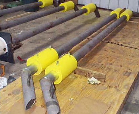
Figure 1 - Shunted current density sensors circa 2000
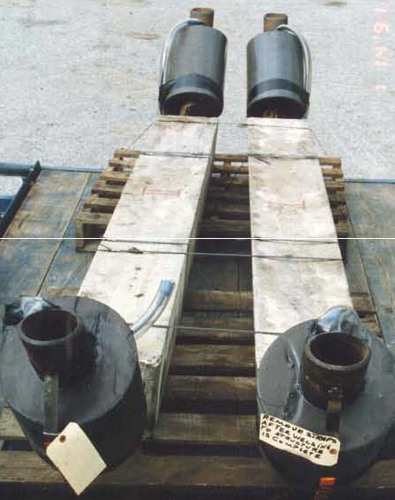
Figure 2 - Anode current monitors circa 2000
Data gaps
Ironically, the most in depth quality cathodic protection data exists in deep water. There is a real gap in our knowledge in shallow water. We know that current cathodic protection designs perform well, however most professionals involved in offshore cathodic protection design would agree that the designs used are ultra-conservative. The opportunity to save millions of dollars annually on shallow water cathodic protection is being missed because we don't have the field data. New monitoring approaches can be used to cost effectively monitor new installations and perhaps more importantly anode retrofits (Figure 3). Figure 3 shows a monitored retrofit anode assembly recently deployed on a pipeline retrofit in the Gulf of Mexico.
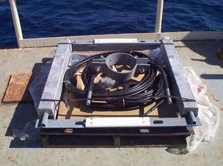
Figure 3 - Monitored anode pipeline retrofit assembly circa 2000
New structure types
Looking at some of the novel new structure types being used to produce deepwater oil and gas, we can see new reasons for and ways to test and monitor cathodic protection.
Subsea equipment - This broadly classifies equipment located on the seabed, often with no on surface component. A typical subsea well head assembly is shown (Figure 4). These structures are maintained against corrosion by a combination of cathodic protection, coatings and corrosion resistant materials. When there is no surface structure, the operator will typically use portable, usually ROV deployed sensors, to monitor cathodic protection. A new generation self-contained cathodic protection probe is shown in (Figure 5). This probe is rated to 10,000 feet of sea-water and can perform contact cathodic protection measurements; the potential and check potential being displayed on the integral LCD readouts. The instrument can be adjusted to interrogate fixed stab, cable-less sensors (Figure 3). These sensors contain an encapsulated shunt that allows current and current density information to be measured. One internal readout displays the shunt reading and the other displays potential. This instrument has been specifically designed for deepwater ROV use. The power is controlled by a photo sensor, which powers up only when illuminated by the ROV video lighting. The instrument has no electrical interface to the ROV and can thus be included in the subsea tool rack for periodic use when opportunity presents itself.
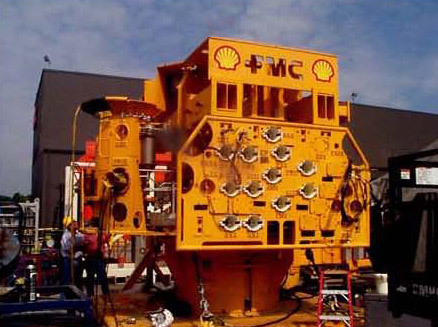
Figure 4 - Subsea well head assembly
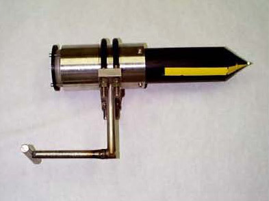
Figure 5 - Self-contained cathodic protection testing probe for ROVs circa 2000
New systems being utilized in the North Sea and other parts of the world are using high tech subsea modems that are able to modulate signals through the pipelines and flow-lines themselves. Limited usage for corrosion monitoring has proven to be largely successful. As these systems develop, there will likely be more and more application in the corrosion and integrity monitoring sectors. Some of the most critical cathodic protection monitoring for these structures happens on dry land, particularly, verification of electrical continuity on the structure. This subsea equipment is easily the most mechanically complex equipment ever deployed on the seabed for periods of 20 years or more continuous immersion. Mechanical fastenings, connections and other linkages present possible areas of concern. Many parts have to be either continuous or isolated by design. Among the problems that arise is the false assumption that a threaded connection will ensure continuity. Continuity inspections are critical. There are no industry recommended practices for continuity inspections as of this issue date, however an informal procedure is available (2).
Floating production systems - Floating production systems are, as the name implies, self contained drilling and production structures which float on the surface. They are tethered to the seabed by a variety of methods. Structure types include Tension Leg Platforms (TLP's), floating SPAR structures and semi submersible type drilling rigs which have been converted for permanent mooring. A SPAR structure is shown floating on it's side prior to tow out in a Texas fabrication yard (Figure 6). These complex structures present a number of new CP environments that have rarely been encountered. In order apply cathodic protection efficiently, we have to monitor.
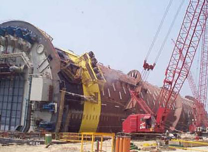
Figure 6 - SPAR under construction, lying horizontal
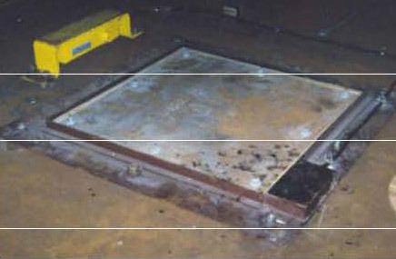
Figure 7 - Current density sensor and dual reference electrode for use with SPAR structures, circa 2000
Floating structures often incorporate moonpools, which are large apertures extending from above water through the hull of the structure. In these areas deepwater drilling and production operations can be completed in a calm, controlled environment. On a SPAR structure the bottom opening of this "hole" could be 600-700 feet below the surface. In addition, they are often full of drilling and production risers and riser buoyancy structures. The exposed surface areas are very large and access for post-installation retrofit or even routine inspection, are limited or non-existent. Due to the very recent installation of these structures, no long-term cathodic protection field data exists. Current density sensors, anode current monitors and dual element reference electrodes (Figure 7) were installed on a recently launched structure in the Gulf of Mexico to provide some answers for future designers.
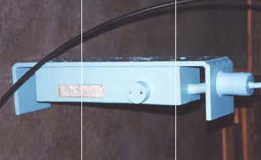
Figure 8 - Zinc reference cell, circa 2000
Variable ballast tanks - Tethered floating structures must have variable buoyancy to adjust for differing deck loadings and sea state. Large tanks in the hull that can be flooded or evacuated provide control with seawater. These tanks are constantly being polarized and depolarized by the installed cathodic protection system which has to last the entire design life of the structure. If there should be a problem and corrosion were to perforate these tanks or the ballast control piping within the tanks, the structure could be placed in jeopardy. Rugged zinc reference electrodes located within these tanks provides long term verification of cathodic protection performance in a cost efficient manner (Figure 8).
Pipeline cathodic protection monitoring
ROV monitoring - Most offshore pipeline cathodic protection monitoring has to be performed by portable means. ROVs inspect offshore pipelines routinely and the three-electrode inspection method (3) is still the most widely used. One recent advance is the modification of these systems that allows for interfacing with fiber optic data telemetry. Cathodic protection testing systems must have some copper-analog conductors to connect remote and close cells in a typical three electrode set up (Figure 9). However the subsea control computer on the ROV keeps this requirement to a single conductor which need extend only as far as the ROV tether management system. All other signals are optically encoded subsea transmitted absolutely error free through the ROV umbilical, and then decoded topsides.
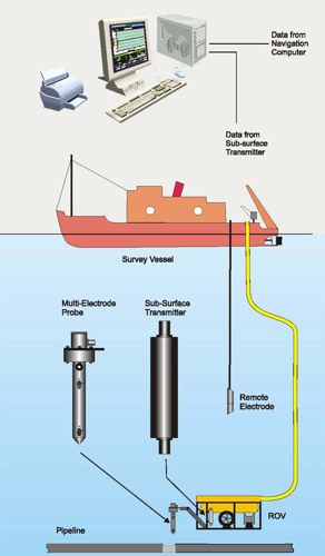
Figure 9 - Three-electrode set up for monitoring cathodic protection on pipelines (courtesy Subspection Ltd.)
Fixed monitoring - Some pipelines are so critical that extraordinary measures are employed to ensure that cathodic protection is adequate. A recent pipeline installed in the Gulf of Mexico was required to operate at 300°F, and because this was an industry first, most of the cathodic protection design parameters were determined in the laboratory. To obtain field data, a complex system of on-pipe sensors was deployed to verify cathodic protection system performance. The monitoring package included current density sensors, temperature probes, anode current monitors, coating efficiency monitors and a variety of reference electrodes. The sensors were deployed at critical locations on the pipeline and cabled back to the surface platforms on either end. Data acquisition systems on either end of the pipeline collected the 58 channels of information. Figure 10 shows one of the two data acquisition panels, and Figure 11 shows a typical sensor array attached to one of the pipeline risers.
Information from this system as well as some point data from diver stabs have been used to verify a predicative model which was developed as part of the scope on this project. The predictive model can now be used with a much higher degree of certainty, and will thus save the operator from costly over-designs and frequent monitoring.
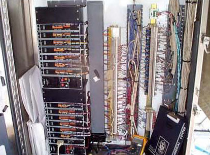
Figure 10 - Data acquisition panel
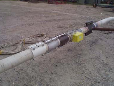
Figure 11 - Sensor array on pipeline
Future developments
It is probable that the development of new thermally applied metallic coatings will be a part of future deep water or high temperature cathodic protection systems. Large capacity mid-depth systems will certainly shift more toward impressed current, as cost and flexibility become more important factors. The future success of these systems will depend largely on information gathered from monitoring systems installed on the early deployments of the technology.
References
1. Townley, D.W., "Unified Design Equation for Offshore Cathodic Protection", paper no. 97473 presented at CORROSION/97.
2. "Inspection Methods to Verify Electrical Continuity on Subsea Structures", Deepwater Corrosion Services, Inc., In-House Recommended Practice-020, 1993.
3. Britton, J., "Continuous Surveys of Cathodic Protection System Performance on Buried Pipelines in the Gulf of Mexico", paper 92422 presented at CORROSION/92.
Want to receive an email when Deepwater publishes new corrosion-related technical papers, case studies, and more? Sign up for our Corrosion Newsletter using the form below. You can unsubscribe at any time.


