Technical article
Strategy and results of an impressed current cathodic protection retrofit in the North Sea
by Edgar Rodrigues, Alex Delwiche, Tim Queen

Abstract
An oil drilling and producing jacket was installed in the North Sea in 1980, 100 miles off the coast of Scotland in 160 m depth seawater. The jacket has 8 legs and was installed with traditional standoff galvanic anodes. Surveys from 2010 to 2013 indicated a reduction in corrosion protection from the cathodic protection system, and plans were implemented to upgrade the cathodic protection (CP) system.
A remote anode sled impressed current cathodic protection (ICCP) system was selected, installed and commissioned in early 2016. This paper discusses the design process and challenges in choosing what was at the time, the largest ever cathodic protection retrofit in terms of delivered current capacity offshore, and the actual current the structure required to maintain protection.
Introduction
The North Cormorant jacket was constructed in the late 1970s and installed in 1980/81 with production start-up in 1982, as seen below in Figure 1. The platform is an eight-legged steel piled jacket. There are five pipelines that run out of the jacket. The CP design was traditional stand-off galvanic aluminium alloy anodes to protect the external un-coated steel from corrosion. No coatings were applied other than at the splash zone, risers and perhaps some appurtenances.
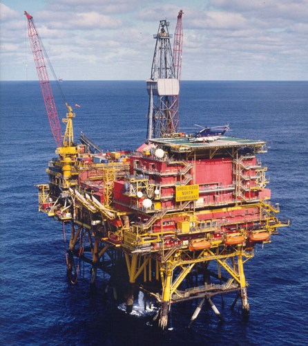
Figure 1 - Typical offshore oil and gas structure
The platform is still viable and serves as a critical hub for major fields in the area. Based on this utility, the operator required a further 20-year life. In 2007 surveys showed that the lower sections of the jacket started to see low levels of protection, i.e. more positive than -800 mV Vs Ag/AgCl/seawater reference electrode, which is the minimum criteria for carbon and low alloy steels, although -900 mV should be sought where possible for an efficient CP system. (1, 2)
Later surveys revealed increasingly lower levels of protection including relatively reasonable levels of protection in 2011, until a survey in 2014 showed large areas of the structure to be inadequately protected, where potentials of around -680 mV vs. Ag/AgCl/sw were recorded on parts of the structure. To term the phrase, the CP system had “dropped off the edge” as can be seen in Figure 2, from the 2013 and 2015 potential readings taken on a gas riser, and in Figure 3, from the 2014 and 2015 average potential readings at differing elevations on the whole jacket. The CP system had served its design life and for the jacket to remain corrosion free, the CP needed to be upgraded, and therefore a retrofit was required for the additional 20-year life requirement.
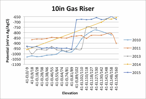
Figure 2 - Example of CP Potential “Dropping Off” in 2013 and 2015

Figure 3 - Average Potentials Vs Over Time for Varying Depths (from COABIS inspection data)
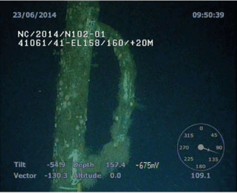
Figure 4 - Example of depleted anode at EL158
Design strategy
A number of design concepts were already underway by then, led by the operator knowing that at some time soon the CP system was going to be ineffective. These designs included galvanic and ICCP retrofit options.
However, it was important to understand the surface area and current requirements for retrofitting or upgrading the CP system. As the structure was pre-electronic drawing era, the daunting task of calculating the surface area was undertaken several times from old scanned copies of the original drawings. This led to the first issue, what is the true surface area? It was calculated to be in the region of between 75,000 and 85,000 m2 of bare steel structure including the risers, conductors, appurtenances etc. Some allowance was also made for the surrounding pipelines and buried wells, but in the scheme of current requirement, the bare jacket structure was the fundamental source of surface area.
Having established the surface area, turning to the standards for current density values, typically (1, 2, 3), to support the design, would result in a conservative CP system. There is currently no guide or standard for offshore retrofit CP designs. Using two of the common standards at the time,(1, 2) established that the minimum current requirement should be in the region of 7000 to 8000 A based on a mean current density range 80 to 100 mA/m2. (The two standards have different current density values at differing elevations)
The difficulty with the design process is that this goes through a series of iterations and developments as the cost of the total installed project is closer defined, meanwhile the structures CP system is failing year on year. The dilemma being, how much contingency does one add in to account for re-polarisation of the existing system? How long will take the system to re-polarised? When will the retrofit system get installed and commissioned? These were perhaps the most challenging aspects of the design and project schedule.
Using the standards then to establish what requirements would be in the worst case, full repolarisation, would have over complicated the design and put a budget cost of the total installed project, out of reach. In addition, looking at the magnitude of the CP retrofit to meet the current required, it was soon established that real estate on the seabed and topsides was at a premium and because of this limitation and the financial implication, the designers were led to justifying an optimal solution. As such the CP design used some useful literature(4, 5, 6, 7, 8, 9). The purpose of this paper is to establish whether these are a reliable source and whether the data collated from this project can further reduce any future CP upgrades, and thereby drive down the overall install cost, on fixed subsea assets.
For a polarised structure, the current required to maintain protection is dependent on many factors including depth, temperature, flowrate and burial conditions. Previous studies in the North Sea such as that conducted on an operational hybrid CP system5 showed that at -925 mV the average current density was approximately 70 mA/m2 with a standard deviation of approximately 36 mA/m2. These values were observed after the system had been operational for two years. On another structure (7, 8, 9) average figures of 50-80 mA/m2 with corresponding typical potential levels around -900 mV were observed. Even lower values of approximately 30 mA/m2 with a corresponding least negative potential of approximately -850 mV were observed during another study on the same structure at a later date.
Given an allowance for repolarisation of those areas already under protected, a 7500 A system was established, ironically sized as if the mean current density values from the standards had been used. Would this be enough if depolarisation and low levels of CP was continuing?
To establish this current requirement would have been challenging with a galvanic anode system. This would have required adding over 600 gross tonnes of anodes to the structure, a daunting challenge given the advanced age of the structure. This would have required removal of some of the original, now depleted, anodes. There simply was not sufficient space on the seabed to deploy aluminium anode sled structures, therefore after an initial conceptual design, this option was abandoned in favour of an ICCP solution.
A CP monitoring system was also considered during the design stages.
The financial constraint in any North Sea project is the offshore time, particularly vessel costs, therefore the CP system type had to be quick and simple to install. A modified version of an ICCP anode sled used on previous occasions was developed to produce 950 A. This reduced the number of units subsea, topside and cable protection systems. 8 No. sleds could now be remotely spread around the structure, rather than the 900 No. plus galvanic anode solution. Each ICCP anode and cable took 12-16 hours to install. To date of submitting this paper, this is the largest CP retrofit with ICCP in terms of total output capacity.
The installed ICCP system was energised in 2016. Dropcell potentials were taken to balance the system and give an indication of the potential levels before and during the energisation of the system.
There are a number of dangers when it comes to providing ICCP to offshore fixed structures that were considered in the design and planned into the execution and on-going operation of the ICCP system. One concern was overprotection, and therefore it was deemed necessary to maintain a level of protection that when measured, did not exceed a certain level, thereby giving some contingency and reassurance that where those areas were not being measured, the potential levels remained within given parameters. This is an important part of the design, as this had an implication into the management of how the ICCP system was set-up.
Results
Due to some operational issues with the monitoring systems that were installed as part of the ICCP project retrofit, dropcell surveys were carried out to measure the potentials of the jacket and assess the CP system.
The dropcell potential plots can be seen in Figure 5, before and after energisation. The potentials shown were taken four days after energisation and adjusted to their final settings, of 4200 A. On average the potentials shifted 200-250 mV electro-negatively after 4 days on. After 5 months of operation a further dropcell was undertaken and a further 100-150 mV polarisation had taken place.
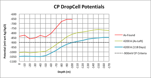
Figure 5 - DropCell Potentials for Varying Depths
A ROV survey was also taken in 2016, one month after the system had been energised that took a small number of stab potentials at various elevations. The average potentials at each elevation now includes these records, Figure 6.
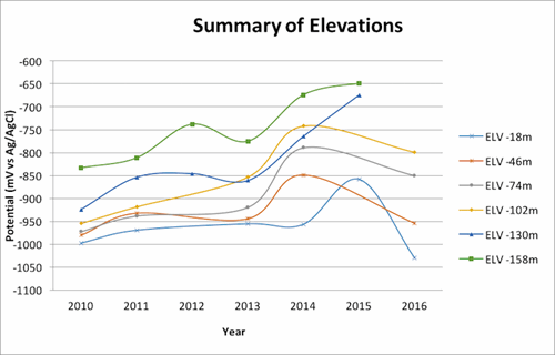
Figure 6 - Average Potentials Vs Over Time for Varying Depths Updated
Strategy and results of an impressed current cathodic protection retrofit in the North Sea
by Edgar Rodrigues, Alex Delwiche, Tim Queen
ABSTRACT
An oil drilling and producing jacket was installed in the North Sea in 1980, 100 miles off the coast of Scotland in 160 m depth seawater. The jacket has 8 legs and was installed with traditional standoff galvanic anodes. Surveys from 2010 to 2013 indicated a reduction in corrosion protection from the cathodic protection system, and plans were implemented to upgrade the cathodic protection (CP) system.
A remote anode sled impressed current cathodic protection (ICCP) system was selected, installed and commissioned in early 2016. This paper discusses the design process and challenges in choosing what was at the time, the largest ever cathodic protection retrofit in terms of delivered current capacity offshore, and the actual current the structure required to maintain protection.
A ROV survey was also taken in 2016, one month after the system had been energised that took a small number of stab potentials at various elevations. The average potentials at each elevation now include these records, Figure 6.
Related Content
Spotlight

Lufeng 13-2
Project case study: Two RetroBuoy™ systems for a fixed platform in the South China Sea
Read more


Technical papers
