Technical Paper
Monitoring cathodic protection system performance in deep water production systems (Part 2)
BY JIM BRITTON (2005)

This paper was originally written for the Corrosion 89 conference, put on by NACE. It was subsequently published in Materials Performance in 1990. In 2005, Mr. Britton wrote an update to address the changes in corrosion control technology for deep water production equipment that had taken place in the interim.
Part One: Monitoring CP System Performance in Deep Water Production Systems (1989)
Original abstract
Increasing interest in deep water offshore areas has presented a whole set of new unsolved problems to the corrosion industry. Several programs are in progress which are attempting to formulate revised cathodic protection design criteria for the deep ocean. The lack of historical data, combined with the increased criticality of accurate corrosion control design in these areas, serve to accentuate the need to be able to monitor the performance of the cathodic protection system once installed. The structural designs being considered for deep water production also present new problems which cannot always be addressed with standard monitoring methods and technologies. This paper will identify some of these problems and offer some generic solutions which should serve to increase the overall reliability of future deep water corrosion control systems.
The key differences with deep water operations
In many cases it is not the actual water depth but rather the nature of the production hardware that determines optimum maintenance and inspection strategies. For example truly deepwater fields (> 1000 M) there are two basic options for hardware selection:
1. Use “wet trees” and send production back through flow lines to a host production facility (Floater or Fixed Platform).
2. Use “dry trees” produce from floater in relatively close proximity to wells.
In either event there will be one thing in common, ROVs will be the main tool for the majority of corrosion related subsea inspection and monitoring tasks. Thus we must determine where they can best interface into the scheme.
If a floater, which could be anyone of a number of configurations, is used. There will normally be additional classing society regulated inspection requirements. These will include hull integrity monitoring requirements not found on fixed production systems. Part of this process, normally termed In-Service Inspection, is a periodic “UWILD” or Underwater Inspection In-Lieu of Dry-docking. It is these regulated inspections where most hull and mooring system CP monitoring is achieved. These inspections are normally performed with an ROV, even though they are largely in diver depth range. The reason for this being overall efficiency of using a machine rather than a person.
Basic monitoring options
As with any other cathodic protection or corrosion monitoring application there are two general strategies, the most successful programs incorporate a combination of the two.
1. Portable monitoring - Measurements made using portable instrumentation.
2. Permanent monitoring - Measurements made with permanently mounted sensors.
There are a host of pros and cons between the two methods [1]. But let's focus on the true strengths of each method.
Portable monitoring
Can provide a comprehensive survey of CP status, at time of inspection, over a large percentage of the structure where access with a portable device is practical. This is the preferred method for the following applications:
1. Baseline surveys
2. Calibration of permanent devices
Permanent monitoring
Provides the ability to remotely monitor system status, on a time base, with absolute point repeatability. This adds a predictive value to the data allowing trends to be more meaningfully tracked. The monitoring exercise is largely de-skilled with permanent systems giving a generally higher level of data reliability. Human and/or instrument calibration errors are eliminated. Having set the stage a quick review chronology of key advances (and dead ends) in the Offshore CP Monitoring business would be as listed below. Many of these innovations are described in greater detail [2] [3].
Brief chronology of CP monitoring of offshore corrosion
Circa 1972 First permanent monitoring systems (hard wired) installed on offshore structures. Mainly just reference electrodes. North Sea.
Circa 1975 First attempts to use acoustically linked data transmission. Never really practical due to battery life and cost. North Sea.
Circa 1979 First practical ROVs with CP inspection capability and useful operational reliability. Main interest is on pipeline inspection to provide alternate to trailing wire inspections, known to be inaccurate. Early Probes were interesting affairs. North Sea.
Circa 1980 First three electrode survey performed on an offshore pipeline. This became survey method of choice for offshore pipelines, still in use today. North Sea.
Circa 1984 Improved contact ROV probes allow direct interface without digitizing. Gulf Of Mexico.
Circa 1985 First permanent offshore current density sensors deployed Gulf of Mexico.
Circa 1986 The first self bleed Zn – SW permanent reference electrode was installed. Reliability improved dramatically. Gulf of Mexico.
Circa 1988 First twin-element probes put into service. Still the most widely used contact probe for ROV. Gulf of Mexico.
Circa 1990 First reliable anode current monitors and current density sensors deployed on deep fixed offshore structures. Gulf of Mexico.
Circa 1997 First Deepwater Self-Contained ROV CP measurement system. Gulf of Mexico.
Circa 1998 Systems installed using subsea modems to transmit data in offshore pipelines.
Circa 2000 Self Contained ROV CP Measurement System modified to present form. Gulf of Mexico.
Circa 2000 The ultra-rugged reference electrode conductor was developed. Gulf of Mexico.
Circa 2004 The invention of the solar powered subsea test station. Gulf of Mexico.
Portable surveys
Most of the instrumentation used for portable surveys is confined to the use of reference electrodes for potential or field gradient monitoring. The present systems used for ROV interface can be broadly divided into two types; Integrated and Self Contained.
An integrated instrument will send data to the surface as an analog or digital signal to be read on a surface instrument or logging system. This is the basis of most subsea pipeline inspection systems and much general purpose CP probes (Figure 1).

Figure 1 - Twin Element Contact Cathodic Protection Probe (for ROV)

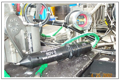
Figure 2 - Self-contained cathodic protection measurement system. A self-contained system has no direct-wired interface with the ROV system, and merely uses the ROV as a transport and video eyeball for the system.
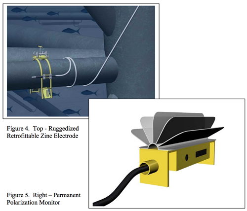
Figures 4, 5
Hard wire
The surface hard wired systems can be used in areas where getting the cables to the surface is relatively simple and inexpensive or where it is desirable to have on-line on demand access to CP performance data. Other areas where hard wire to surface is preferred are:
1. In conjunction with impressed current cathodic protection systems.
a. FPSOs
b. Drill ships with deep-water drilling riser systems.
2. Where external subsea readout would require a hull penetration.
a. Seawater Ballast Tanks.
Hard wire system economics
1. More than 75% of the cost to deploy and wire a surface hard-wired instrument is in the cost of the electrical cable and the installation of the cable and instrument. Only about 20% - 25% of the cost is in the instrument.
This means that these permanent sensors must be rugged and reliable. Do not use "cheap" or untested instruments. Use Combination instruments wherever possible to save on number of cables. Fig. 5.
Once in place a typical hard-wired system will pay for itself many times over in reduced offshore man-hours, shifting the task and man-hours to an onshore data management function.
This provides significant HSE benefit by eliminating un-necessary personnel exposure to the hazards of an offshore production facility.
Subsea visual indicators
Introduction
The evolution of this device from within the authors company was a natural progression. When a company works closely with the Deepwater ROV industry two things become apparent:
1. There’s no ambient light in deep water.
2. Without a video-camera you are blind and of zero worth.
So all ROVs by definition have lights and cameras (Figure 5). Hence the original idea of using a light activated power-up for ROV instruments. This was very successful, and is still in use, extending battery life in the portable instruments to better than 6 months without charge or replacement.

Figure 6 - All ROVs have lights and cameras
SunStation™ light-powered subsea readout applications
The light-powered readouts should be located at points where ROV intervention is expected to be regular. Thus advantage can be taken of this visitation and a FREE inspection secured on the recorded record of the intervention. Some such points would be:
1. Wellhead ROV control panels.
2. Mooring attachments.
3. Dynamic equipment, risers.
4. Pipeline termination or connection skids (PLETs or PLEMs).
The solar readout contains all information pertinent to the location of the sensors and the specifics of the value displayed. This information is contained on a simple bezel around the display (Figure 6). The ROV Video Overlay will impose other relevant information such as time and date, water depth and a verification of location often with XY coordinates.
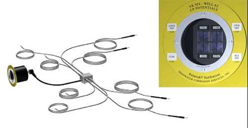
Figure 7 - Typical first generation SunStation solar readout configuration – 4- channel – bezel contains location and readout unit information
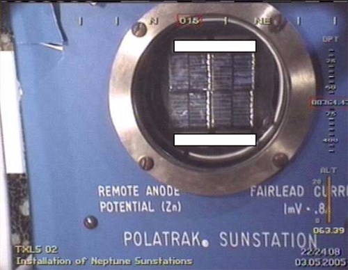
Figure 8 - Offshore retrofitted unit; The subsea image recorded on the DVD provides a complete record of the inspection event with no additional data recording required.
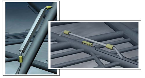
Figure 9 (left) - Monitored anodes can be output to solar readout.
Figure 10 (right) - Dual-element reference electrodes can be output to solar readout.
The future of cathodic protection in deep water
Here we go into the unknown. However, the author’s prediction of where the state of the art will move in the next decade is as follows, (based on the leading edge applications currently being deployed in the deep water Gulf of Mexico.)
1. More use of impressed-current to protect floating production hulls and mooring terminations. As the structures become larger and more complex, the cost and weight-saving advantages of ICCP will ultimately win through.
2. Use of dedicated smart anode structures Fig. 10. Fig 11.to protect multiple subsea elements. The subsea displays will be the status indicators and will de-skill CP management to a routine meter reading task. This is the most efficient way to use and manage sacrificial anode systems in deep water.
3. Move toward permanent monitoring rather than portable. This will be accompanied by routine use of satellite data transmission to allow global access to records, and to facilitate automatic internet-based regulatory reporting. This will mirror other asset integrity management initiatives geared toward developing event-based rather than interval-based programs.
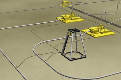
Figure 11 - Smart sacrificial anode pods will protect multiple structures
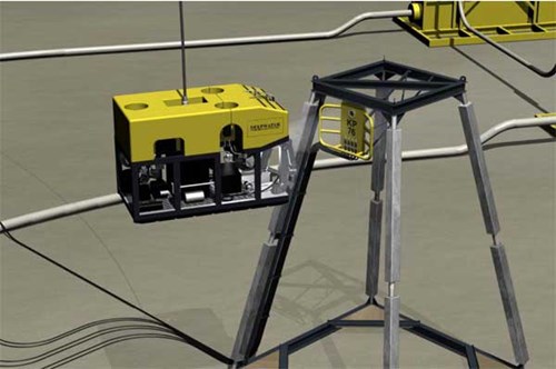
Figure 12 - One ROV can read the entire system status from display panel
Want to receive an email when Deepwater publishes new corrosion-related technical papers, case studies, and more? Sign up for our Corrosion Newsletter using the form below. You can unsubscribe at any time.
Related content
Spotlight

Monitoring CP performance in deep-water production systems
Increasing interest in deep water offshore areas brought a whole set of problems to the corrosion industry.
Read more

Technical papers


