Technical Paper
New paint preservation technologies for offshore and marine equipment
by Jim Britton (1998) from NAVY Conference

Introduction
Offshore and marine operators, without exception, spend the largest part of their corrosion budgets on paint maintenance. The failure of a “well applied” paint system can be traced to a few basic failure mechanisms. Some of these mechanisms are addressed in this paper. If the solutions presented are applied, then paint systems will last much longer, and maintenance budgets can be diverted to other areas.
The systems presented are no substitute for poor, out of specification, surface preparation or application. The writer therefore, would always recommend using qualified paint inspectors during the initial coating of any marine structure. The mechanisms presented do not represent a complete list, but do reflect some of the more common problems.
Pipe flange corrosion
Pipe flanges are a built-in failure point on any piping system exposed to a marine atmosphere. From day one, when the flange is initially assembled, coatings on the inside hidden surfaces of the flange are damaged by the fasteners which hold the flange together. Once a flange is assembled, there is no way to paint these inner surfaces, but salt water and free oxygen intrusion, ensure that corrosion is free to occur. The result is unsightly corrosion products leaching from the flange gap and dripping onto other coated surfaces [Fig. 1]. The ultimate result could be the failure of the joint from either fastener corrosion [Fig. 2], or gasket seal corrosion.
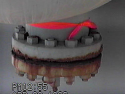
Figure 1 - Typical flange corrosion
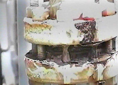
Figure 2 - Fastener corrosion can result

Figure 3 - Newly installed flange protector (note early crevice corrosion)
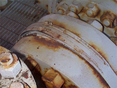
Figure 4 - Crevice corrosion develops, begins to distort band
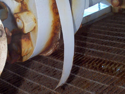
Figure 5 - Band eventually fails leaving a badly corroded flange
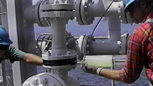
Figure 6 - Painters applying FLANGESEAL on an offshore platform
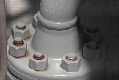
Figure 7 - Flange fasteners show early signs of paint failure within months
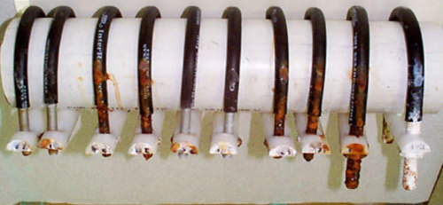
Figure 8 - Rack of pipe U-Bolts exposed for 2,500 hrs. in salt fog cabinet. From left to right:
Sealed Aluminum Ceramic, Sealed Aluminum Ceramic, Fluorocarbon (With Primer Vendor A), Fluorocarbon (With Primer Vendor A), Sealed Aluminum Ceramic, Sealed Aluminum Ceramic, Fluorocarbon (No Primer Vendor A), Fluorocarbon (No Primer Vendor A), Fluorocarbon (No Primer Vendor B), Hot Dip Galvanized
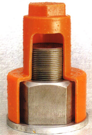
Figure 9 - HDPE fastener protector cap
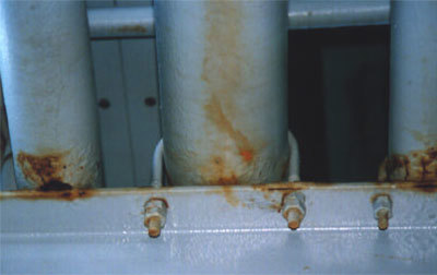
Figure 10 - Pipes on pipe racks invariably have crevice corrosion problems
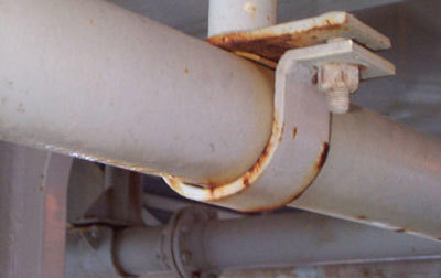
Figure 11 - Pipe saddles and half-saddles create an aggressive crevice and make inspection / maintenance almost impossible
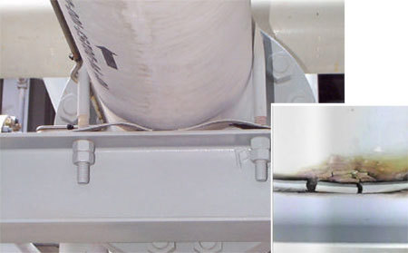
Figure 12 - Rubber pads don’t help, see crevice corrosion (inset)
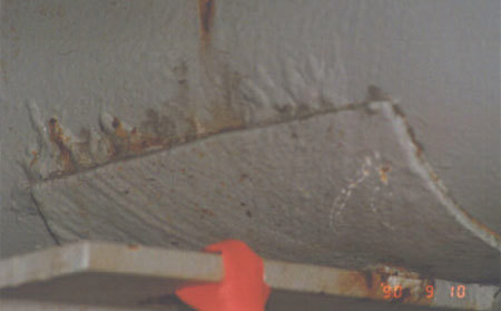
Figure 13 - Contoured fiberglass pads provide tight crevice if improperly sealed
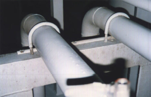
Figure 14 - I-Rods bolted to upper beam surface provide excellent crevice control
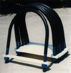
Figure 15 - For easier installation, the rod can be incorporated into the U-Bolt assembly [Fig. 15]. Over 1,000 platforms in the Gulf of Mexico now have I-Rod systems in place.
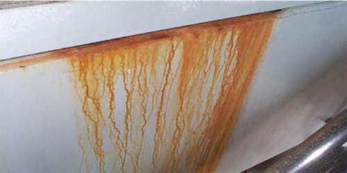
Figure 16 - The rust stains on this tank originate from only 2 sq.in. of corrosion on the upper rim. The stains are unsightly and will eventually casue the paint system to fail.
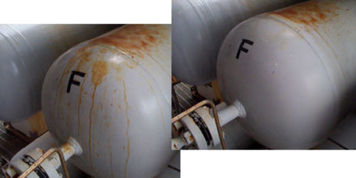
Figure 17 - Before and after using the product "Rig Restore."
Want to receive an email when Deepwater publishes new corrosion-related technical papers, case studies, and more? Sign up for our Corrosion Newsletter using the form below. You can unsubscribe at any time.
Related content


Technical papers


