Technical Paper
Maximizing the value of underwater cathodic protection surveys
by Jim Britton (1994)

Abstract
In the Gulf of Mexico and many other operating areas, the measurement of cathodic protection potentials on offshore structures is a regulated activity. Thus, since it has to be done, it makes sense to get as much benefit from the survey as possible. In the majority of cases this is not being done. I will describe here some fundamental requirements for accurate surveys as well as some new approaches to the task which greatly enhances the survey value at little or no additional cost.
Types of cathodic protection survey
For the purposes of this paper, only platform surveys with galvanic anode CP systems will be considered. The types of survey performed may be broadly categorized as follows:
1. Surface-deployed potential survey - Often referred to as 'drop cell' surveys. A portable reference electrode is dropped in even depth increments through the structure. The data is displayed on a topside meter and hand recorded. This is the least accurate of the survey techniques and is also the least expensive. This type of survey is performed annually and is used as a general potential survey only.
2. Diver or ROV-assisted potential survey - This type of survey – part of a level II or level III inspection – is the main topic of this paper. The reference electrode is positioned with divers or an ROV. Signals are normally displayed on a surface meter and may be recorded manually or on a computer. This type of survey is performed periodically (every 3 to 5 years) depending on the structure type and location.
3. Diver or ROV detailed survey - Some operators require more than just cathodic protection potentials; they want anode current output and sometimes cathodic current density data. In these cases, more complex gradient-type survey systems are available [1]. This paper will not go into much detail on these types of surveys since they are normally restricted to special cases in deep water and are considerably more expensive.
Purpose / Goals of cathodic protection surveys
Before we can fully appreciate the critical elements which produce a successful cathodic protection survey, we must first appreciate why the survey is being performed in the first place. The reasons why are listed below, in no particular order:
• Regulatory compliance
• To verify adequate CP system performance
• Retrofit planning and budgeting
• Hot spot identification
• Design calculation verification
In order that these goals can be achieved, the cathodic protection survey must be planned and conducted with the following philosophy in mind. It has often been stated that cathodic protection is a black art. This is not true but A.R.T. does describe the key elements of a successful survey:
• Accuracy
• Repeatable
• Thorough
The A.R.T. of the cathodic protection survey
Accuracy - The accuracy of the cathodic protection survey is of paramount importance. Misleading data can Iead to costly decision errors. The accuracy of the survey is controlled by:
• Equipment quality
• Calibration procedures
• Operator proficiency (diver or pilot)
Repeatable - Repeatability and accuracy go somewhat hand in hand. However, repeatability of a survey is largely controlled by:
• Survey procedure quality
• Survey technique
• Equipment design
Thorough - The need to be thorough is obvious. We don't want to overlook any problem. It should, however, be stressed thal being thorough does not mean that every single member and anode on the platform has to be checked, but a representative sample at each elevation must be looked at. Thoroughness Is controlled by:
• Survey specifications
• Data recorder proficiency
Now we have the basic requirements identified. Let's get into the details a little more.
Equipment quality
The main basic pieces of equipment which must go offshore are:
• Reference electrodes (CP probes)
• Voltmeters
• Electrode cables (umbilicals)
• Ground wires and clamps
• Calibration equipment
The cardinal rule is 100% REDUNDANCY; never go offshore with only one of anything. If it can go wrong, then it probably will.
Reference electrodes (cathodic protection probes)
The reference electrodes are the key pieces of equipment on the spread. There are many points concerning reference electrodes about which a large percentage of offshore inspectors are misinformed. I will attempt to focus on some key points regarding cathodic protection probes.
What is a reference electrode? - A reference electrode is an electrochemical device, which as the name implies, is a reference (known) voltage source against which unknown voltages are compared. The unknown voltages in our case are those at points, between the surface of the platform and the sea water. The (known) reference voltage used in offshore work is that between pure silver (Ag), and a saturation of its chloride salt (AgCl). thus when a cathodic protection potential is reported it will normally be written:
(-)0.935 Volts vs Ag/ AgCl or 935 mV (-) vs Ag/ AgCl
A schematic cathodic protection reading hook-up is shown in Figure 1 below. Note that the polarity of the reading is negative; this is a convention which is observed by all corrosion engineers. it is much more important when dealing other types of cathodic protection systems where polarity reversals may occur under certain conditions. Systems should always be connected as shown.
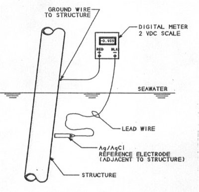
Figure 1 - Schematic cathodic protection potential measurement
Reference electrodes– Ag Ag Cl in particular – are very susceptible to damage which will cause them to lose accuracy or fail to work entirely. Below is a practical list of do's and don'ts which will ensure accuracy and avoid costly equipment damage.
DO's
• Use only twin element working electrodes
• Calibrate frequently, following manufacturers recommendations
• Store electrodes in clean sea water in a plastic container while offshore
• Store electrodes in sealed plastic bags while not in use
DON'Ts
• Immerse electrode with a damaged (copper exposed) lead wire attached or underwater connector broken
• Calibrate in a metal container
• Touch electrode elements with bare hands
• Expose electrodes to oil, grease, solvents or detergents
• Use an analog (moving coil) meter to record potential
• Attempt field repairs
Reference electrode designs - There are a number of reference electrodes on the market, but they may be divided into a few generic types. It is important to select the correct electrode for the job. A brief description of the key features of each type of electrode is given; Figure 2 shows typical electrode types.
Single vs twin elements - The basic difference here is obvious. The twin element electrodes are marginally more expensive, but the advantages are worth the investment. Twin elements allow for online continuous calibration. Thus, if a problem develops, it can be picked up immediately, not at the end of a dive. In the event one electrode does fail, the other may be used to complete a dive and any data corrections can be accurately made.
Drop cells - Normally provided on a Iength of wire 200 - 300 feet long, the cell will normally have a PVC housing which is provided with a sinker weight. Probe perforation will be random.
Proximity probe - As the name suggests the proximity probe is designed to be positioned at the point where the cathodic protection reading is required. The proximity probe is similar to the drop cell but with the following exceptions; It will normally be filled with an underwater connector on a short cable, it will have controlled perforations, either at one end or at a fixed distance from one end.
Tip contact robe - The tip contact probe is the probe of choice for most underwater platform surveys. The probe has a heavy duty non-metallic housing (normally Delrin) and has a small stainless steel tip for making subsea ground connections. The tip should be no more than 1 sq. inch in total area. The unit has an underwater connector and controlled position (normally 1 or 2 inches from tip) perforations.
The perforation distance is critical since it is the position of the perforation relative to the structure which determines the potential recorded.
Bathycorrometer - This is an instrument which has tip contact and an integrated voltage readout so that no wire to the surface is required. These units are used mainly by the military for performing hull surveys.
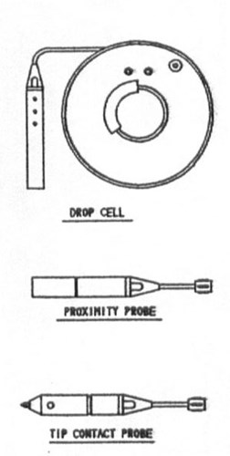
Figure 2 - Types of cathodic protection probes
Voltmeters
The majority of surveys use standard digital multimeters. It is important the meters have a 1mVDC resolution at 2 - 3 VDC and a 0.1 mVDC resolution at 200 - 300 mVDC range. Do not use analog or instruments which may have low input impedence; this will irreparably damage the electrodes.
Newer survey systems use A to D converters, which allow readings to be recorded and stored in a computer This technology is discussed in more detail towards the end of this paper.
Cables
The umbilical cable between the surface and the probe is critical; any damage to the insulation, which exposes the copper conductors, however small, will cause significant reading error. For this reason it is important to use a very rugged wire. The writer's company uses armored diver "comms" cable, which gives excellent service. On ROV surveys, the signal is transmitted in the the umbilical cable, so only a short whip cable is required.
In either type of survey, the reference electrode should be connected to the umbilical through a good-quality underwater connector. all connectors must be blanked when not in use. Special care and maintenance of the connectors is critical to prevent electrode damage. The ground wire must be strong and rugged. If any insulation damage is evident the wire should be changed.
Equipment hook up
When using a twin element electrode, two voltage readouts are required. One readout is displaying the potential. The second is displaying the calibration potential between the two reference electrodes. If the calibration (cell to cell) value exceeds +/- 5 mV, there is a calibration error and the survey should be suspended. Figures 3 and 4 over the page show typical connection schematics for various survey configurations. Note that the pipeline risers have their own separate ground wire; they may not be electrically continuous with the platform.
Calibration procedures
The importance of good calibration procedure cannot be overemphasized; in 90% of cases when the electrode Is out of calibration, the readings indicated are pessimistic. Indeed, the writer Is personally aware of two platforms which were completely retrofitted even while exhibiting potentials better than (-)0.950 Volts vs Ag/AgCl and with anodes only 10% to 20% consumed. The reason was a bad drop cell that was not property calibrated. The most dangerous errors are those which are believable but erroneous values.
Before getting into calibration procedures, I would first like to identify the most common sources of errors. The nature of these sources may help to explain why the calibration procedure is set up the way it is.
Measurement error sources
• Damaged lead wire immersed in sea water
• Underwater connector flooded
• Electrode element failure
• ROV umbilical noise
• Poor or 'noisy' ground wire connection
• Voltmeter failure
• Instrument jumper wires and connections
Shop calibration - Obviously the equipment should all be checked out in the shop prior to going offshore. I will concentrate on the reference electrodes in this section, but all voltmeters and test Ieads should be calibrated in accordance with good practice. Procedures that are required for ROVs are not addressed in this paper.
Bucket electrode calibration - This procedure verifies the accuracy of the electrode elements and the wiring internal to the probe only.
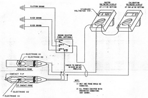
Figure 3 - Standard twin element electrode survey connection schematic
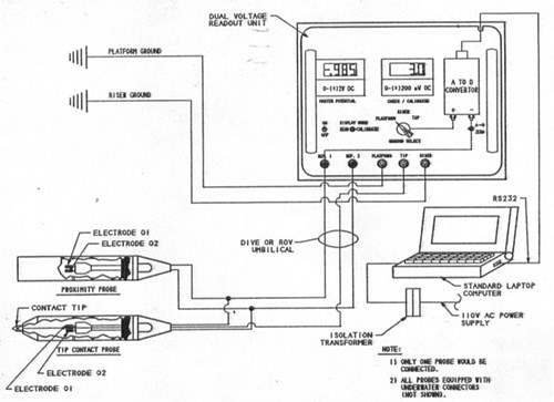
Figure 4 - Typical scanning cathodic protection survey connection schematic
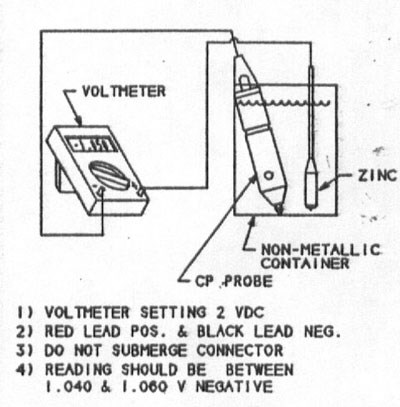
Figure 5 - Bucket calibration procedure for reference electrode
The working electrode is placed into a non-metallic bucket with a zinc calibration coupon. The bucket is filled with artificial seawater (3% by weight artificial sea salt and de-ionized water). When offshore, native seawater may be substituted for this calibration. The zinc calibration coupon should be Mil. Spec. 180001 H material. Figure 5 shows the test setup.
Each of the silver elements should be checked against the zinc; both should read within +/- 5 mV of the same value, which should be within the range (-)1.030 to (-)1.060 VDC. When calibrating a tip contact electrode, the values should be cross-checked using the probe tip in place of the wire to contact the zinc coupon.
Barrel calibration procedure - This is basically the same as the bucket procedure with the exception that all of the umbilical wire and connectors are immersed in the test drum. A large plastic garbage can is a good receptacle. This verifies the integrity of the umbilical and underwater connectors. This procedure should be repeated offshore as the 'pre-survey' calibration, but with the diver or ROV and all of the umbilical in the water.
On-line calibration - Figure 3 shows a dual-element connection schematic; the calibration meter is reading one cell to the other. If they were in perfect condition the reading woiuld be zero, but there will normally be a slight offset of 1 or 2 mV. The data recorder should monitor this offset voltage and record it. At a minimum it should be logged at the start and finish of each dive. The advantage of doing this is that any problem can be seen immediately and the survey can be suspended. Any time an electrode drifts outside calibration limits, replace it with the backup unit. Note that some electrodes require a stabilization period (sometimes up to 4 hours) before survey work can commence. Ensure that electrodes are stored in salt water while offshore.
Ground contact verification
A ground wire installed over rust or coating, or close to a high voltage ground point can give erroneous data. The quickest way to check this is to select two ground points, clean to bright steel and hook to one and then the other with the probe in the water. Both points should have exactly the same value if the probe is stationary.
Operator proficiency
There are two individuals responsible for ensuring a good cathodic protection survey: The diver or ROV pilot and the data recorder. Probe positioning is critical if a good repeatable survey is required. If the cathodic protection probe is not adjacent to the structure under investigation, the reading is not repeatable. Holding the probe one foot away from the structure is not good enough. If it were not necessary to have the probe this close to the structure, we could use a drop cell and leave the divers at home!
The data recorder's responsibility is to ensure that readings are recorded with the probe in the correct position for the type of survey being conducted. The title of this paper is 'Maximizing the value of underwater cathodic protection surveys.' Poor probe positioning and data recording are the easiest and most common ways to minimize of the value of underwater surveys.
Survey procedures
Ensuring a thorough survey
As stated earlier, it is not necessary to survey every single member. It is necessary, however, to survey a representative sample. Platforms should be divided into zones based on the horizontal framing elevations. Each of these zones should be considered a separate entity. Emphasis should be placed on areas where there is a risk of marginal protection levels, as well as some typical anodes and anode supporting members. Risers and skirt piles must also be checked if applicable.
A typical scope of survey may look like the list below on a typical 8-Pile structure in 200 - 250 feet of sea water:
• Outboard side of all main legs from surface to mud line at 10 foot intervals.
• All horizontal braces between main legs at all elevations, each end and center point. Also measure potentials on each anode on these members.
• All pipeline risers from surface to mud line at 10 foot intervals.
• A minimum of two conductors – preferably at least one inside conductor – at 10 foot intervals down to the mud line. Stab with tip probe to verify electrical continuity.
• All skirt piles, stab with tip probe to verify continuity.
• Select a minimum of 2 anodes per zone for cleaning and physical measurement. Ensure that potentials have been previously measured on the selected anode.
Maximizing the value
To this point, the focus has been on basic survey requirements. These guidelines will ensure that accurate and repeatable information is logged. From here, we will show how to get much more from the cathodic protection survey without significantly increasing the amount of effort or cost.
On the first page of this paper, the goals of the cathodic protection survey were listed. Two of the items are of particular interest to many operators because they can directly affect the bottom line. In revisiting this list we can show how conventional surveys meet these goals and where they fall short.
• Regulatory compliance
• To verify adequate cathodic protection system performance
• Retrofit planning and budgeting
• Hot spot Identification
• Design calculation verification
Regulatory compliance - The survey as described fully meets all of the requirements of local Gulf of Mexico regulators.
To verify adequate CP system performance - If adequate cathodic protection performance is defined as "acceptable potential levels," then the survey as described is adequate. If there is a desire to know how efficiently the cathodic protection system is actually working, then there is room for improvement.
Retrofit planning and budgeting - It is in this area that improvement is needed. In order to minimize cash outlay on retrofits while keeping in compliance, there are a number of key points to bear in mind:
• It is not necessary to replace anodes on a one for one basis.
• If the platform potential is allowed to fall below roughly (-)0.850 Volts vs Ag/AgCl, then it will take double the number of anodes to re-polarize the platform as compared to the number required if the retrofit is performed with the potential still at around (-)0.950 Volts vs Ag/AgCI.
• The above difference could occur in a twelve (12) month period ((-)0.950 to (-)0.850 Volts).
It is obvious that a 50% reduction in the number of anodes required could represent a significant amount of money, if the retrofit could be accurately scheduled. This fact has not gone unnoticed by at least one operator (2) (3). However in order to predict when the retrofit can be conveniently and effectively scheduled we need the following additional information from the survey:
• Anode current output (on a meaningful number and distribution of anodes).
• An accurate estimate of anode material remaining (in lbs).
• An accurate estimate of anode length and circumference (on selected andes).
Methods for gathering this information will be discussed later.
Hot spot identification - The survey scope as described, if implemented correctly, will identify all hot spots (low potential areas).
Design calculation verification - The ability to verify system design criteria and calculations will enable future cathodic protection systems to be optimized. From the large number of surveys run, it is clear that the rules for platform cathodic protection design are extremely conservative. There is significant potential to safely reduce the number of anodes initially installed. This again obviously translates into reduced life-cycle cost for the operator.
As more empirical data become available on current density / potential relationships and anode performance, confidence levels to reduce design redundancy will increase. In order to gather this type of information, some minor changes to survey methodology must be made.
Scanning cathodic protection surveys
A scanning cathodic protection survey varies from the basic survey described in the following areas:
• Potentials are logged directly into a computer rather than being handwritten.
• The reference electrode is run along the member under investigation rather than being held stationary.
• Electrode positioning becomes more critical.
• More of the structure is measured and significantly more data points are recorded.
• More emphasis Is placed on anode potential measurements.
This large amount of anode and structure potential information together with some physical anode dimensions makes it possible to calculate the operating anode current output (2). Statistical averaging can then be applied to the total system and with some historical data it is possible to compute current density, total system current and – most importantly – remaining life. One system routinely in use in the Gulf of Mexico is presented as a typical example of a scanning CP survey. The following section with tables and figures shows a typical survey equipment list, survey procedures, data input requirements and data output formats.
Equipment required - Table 1 below shows a typical equipment list:
| Item | Quantity | Description |
|---|---|---|
| 1 | 2 | Dual element Ag/AgCl reference electrode w/ RM3-FS underwater connector, lock ring, and blank. |
| 2 | 2 | Dual voltage readout and A to D converter. Spare A to D Converter module. |
| 3 | 2 | Multimeter |
| 4 | 2 | 300 foot armored umbilical w/ RM3-MP underwater connector, lock ring, and blank. (Not required for ROV surveys) |
| 5 | 2 | Portable computer with survey software, disks and backup system. |
| 6 | 1 | Electrode calibration kit. |
| 7 | 3 | 200-foot Kevlar reinforced ground wire with clamps |
| 8 | 2 | Insulated riser ground clamps |
| 9 | lot | Survey log sheets |
| 10 | 2 | Isolation transformer |
| 11 | 1 | Multi-plug protected outlet |
| 12 | 2 | Pit gauges |
| 13 | set | System operating and wiring manuals |
| 14 | 1 | Spares and maintenance kit |
| Note: For ROV surveys, it is recommended that one of the two electrodes is substituted for a tip contact probe | ||
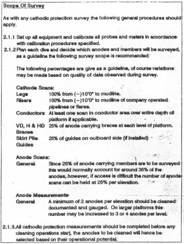
Table 2 - Typical survey scope
Survey procedure - Table 2 shows a section from a scanning system specification which outlines the typical scope of survey.
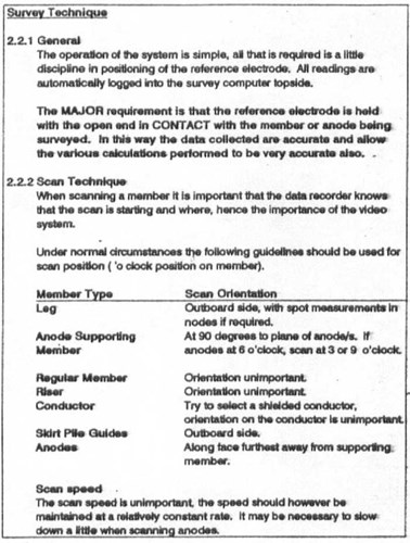
Table 3 - Typical scanning survey technique
Survey technique - Table 3 shows a specification section which highlights some useful techniques.
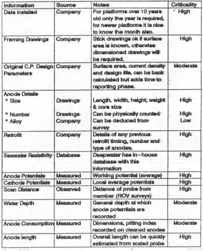
Table 4 - Data input requirements - Table 4 above lists the various pieces of information which must be assembled to allow maximum predictability from a cathodic-protection survey.
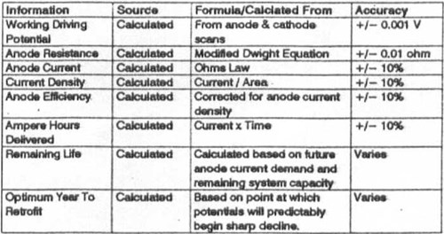
Table 5 - Data outputs - Table 5 above shows the types of data output which are calculated from the input data in Table 4.
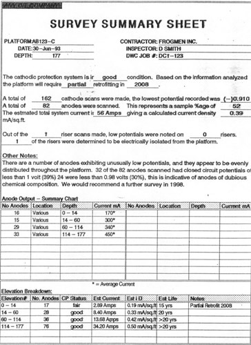
Table 6 - Typical survey sheet
An added benefit of the scanning survey is the ability to produce graphic representations of the information very easily. A typical summary sheet and some survey profiles are shown in Figures 6 and 7:
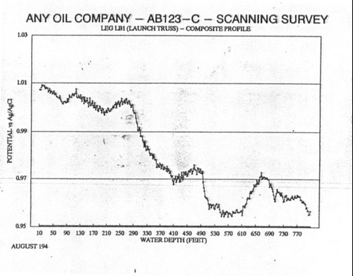
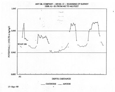
Table 7 - Typical scanning survey plots
Summary
The average cost increase to run a scanning survey rather than a point survey on an 8-pile platform in 200 feet of water is relatively small. The entire cost to survey such a platform (MMS level II ) would be approximately $20,000.00 (in 1994). Thus, a survey cost increase of less than a few percent can yield all this additional information.
References
[1] J N Britton and R J Holt - A Computerized Cathodic Protection Survey System for Offshore Platforms. Materials Performance. VoI 25. No. 4 April 1986.
[2] M W Mateer - Often Overlooked Data Available from a Typical Offshore Subsea Survey CORROSION/91 Paper No. 223 (Houston, TX: NACE, 1991).
[3] M W Mateer - Designing Anode Retrofits for Offshore Platforms. Materials Performance. Vol 33. No. 1 January 1994.
Want to receive an email when Deepwater publishes new corrosion-related technical papers, case studies, and more? Sign up for our Corrosion Newsletter using the form below. You can unsubscribe at any time.
Related content
Spotlight

CP simulation on an offshore platform
CP modeling was used to provide depolarization timeline
Read more


Technical papers


