Technical Paper
Cathodic Protection Surveys of Offshore Platforms - A New Approach
by Jim Britton (1998) from Corrosion98
Abstract
Historically, cathodic protection (CP) surveys of offshore platforms have comprised a number of steel to seawater potential measurements recorded at selected points on or around the structure. Little or no emphasis has been placed on evaluation of the "resilience" of the CP system; i.e. how hard is the system working, how efficiently, and how much longer will it continue to provide efficient protection. The new approach, which has been used by some operators since 1989 in the Gulf of Mexico, addresses some of these areas without significant increase in the time required to perform the inspection.
Introduction
In the Gulf of Mexico and in many other offshore producing areas, government regulations require that cathodic protection systems on offshore platforms are surveyed periodically to verify the adequacy of protective potentials1. In the Gulf of Mexico, most operators perform an annual "drop cell" survey and a diver or Remotely Operated Vehicle (ROV) subsea inspection every three to five years. These surveys are usually performed as a part of a larger scope of work which involves other structural inspections and non-destructive testing.
Drop Cell Surveys - The drop cell survey is performed from the surface and requires that a reference electrode is lowered through the water column adjacent to the platform structure. Readings are recorded at predetermined depth intervals at various locations around the structure. This method is quick and inexpensive, it will give some indication of the surface potentials on the structure. They will not be accurate due to the fact that the reference electrode could be remote from the structure, however, the readings obtained do give a good general indication as to the protective status of the structure. Potentials recorded are generally optimistic so far as cathode potential is concerned; errors typically range between (-)0.02 and (-)0.06 Volts vs Ag/AgCI, depending on sea conditions, water depth and the protective level of the structure. It is fair to say that if a well conducted drop cell survey indicates marginal protective levels, then in most cases, a detailed survey would reveal areas which were below protected criteria. Figure 1 shows a typical silver/silver chloride drop cell. Figure 2 shows a typical survey report from such a survey.

Figure 1 Typical silver/silver chloride drop cell survey

Figure 1A Typical silver/silver chloride drop cell (DC-II model shown)

Figure 2 Typical silver/silver chloride drop cell survey inspection results
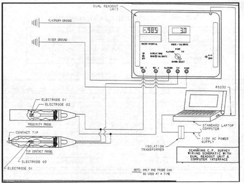
Figure 3 Typical wiring schematic for a good survey set-up
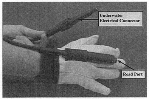
Figure 4 Glove-mounted probe
Survey equipment and personnel
It is virtually impossible to perform an accurate cathodic protection survey with the wrong equipment or personnel. An inaccurate survey could lead to serious consequences with either optimistic or pessimistic inaccuracy. The writer's company has experienced this first hand, having arrived offshore with a dive boat loaded with new anodes only to find that the original CP survey was flawed and that there was no need for a retrofit. Similarly an optimistic survey could result in corrosion damage to the structure. The most common error sources for diver and ROV assisted surveys are:
• Inexperienced survey personnel
• Poor quality silver chloride reference electrodes
• Damage to electrode lead wire insulation from barnacles
• Poor reference ground connection
• Data transfer error
Personnel - One amusing (not for the customer) inspection report viewed by the writer had a beautifUlly laid out report, with hundreds of "potential" readings all recorded in OHMS. If a problem develops it is imperative that the survey data recorder is instantly aware that a problem exists and is trained to take the appropriate corrective action. If a system is obviously marginal or below protected levels, the data recorder should have the ability to collect sufficient information to allow accurate design of a retrofit without having to re-survey.
Reference Electrodes - Silver/silver chloride reference electrodes should be used for offshore surveys. As incredible as it may seem some specifications require the use of copper sulfate electrodes for offshore inspections. Electrode wire become damaged during platform inspections, any exposed copper will immediately impart a positive shift to the recorded potential, the magnitude of which will depend on the location and size of the exposed defect. For this reason it is important to use twin element electrodes connected to a dual voltage readout (Figure 3). In this way any damage to the lead wire will be instantly shown on the calibration meter, and the survey can proceed with the good electrode The electrode should then be replaced for the next dive. The newer high porosity electrode elements perform much better than the old wire dipped type. Of course the design of the electrode housing is important to ensure that the location of the reading is known. Don't use a randomly perforated drop cell for precision surface measurements, use either an open ended probe design (Figure 4) or a probe with calibrated access perforations (Figure 5).
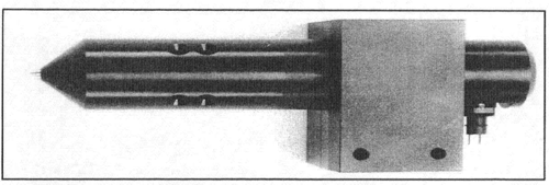
Figure 5 Probe with calibrated access perforations
Recording Instruments - Figure 3. shows a typical wiring schematic for a good survey set-up. Note that there is a dual digital voltmeter display which allows calibration to be monitored both on the electrodes and on the voltage measurement system. The master potential is parallel read through an analog to digital converter directly into a laptop computer. All values can be monitored at all times during the survey, the A-D converter and computer allow error free recording of the large number of potentials required for statistical estimations made in the survey analysis stage. This setup is particularly valuable if an ROV survey is being performed, as any signal contamination from ROV leakage currents or corruption in the high voltage umbilical cable will be instantly recognizable and can be corrected.
Survey method
This section describes some basic survey methodology, where the readings are taken and how they are logged in the field. The next section will deal with data analysis and reporting. The locations described are optimum. In most field situations it is not possible to achieve exactly the locations required but the more data logged the better for statistical analysis. In recent years, the accuracy and repeatability of drop cell surveys has been improved by moving to sintered reference electrode construction and by using dual element electrodes for in-survey calibration.
Diver and ROV assisted Surveys - Typical diver or ROV survey specifications will require that structure to seawater potentials be recorded at all major structural joints (nodes), and at selected locations (often a mid-point) on other members. Normally the main legs will have a potential taken at pre-described depth intervals (10 feet is commonly used). It is rare (but becoming less so) to see specifications which require any potential measurements on anodes or which require that anode current output be measured. Similarly, it is not usual to see requirements for the precise position of the reference electrode during these measurements. Occasionally one will see "within two or three feet of the structure" or "in close proximity to the structure" but rarely "on the surface of the structure" which does actually reflect the true potential value.
A new approach
To call the survey method a new approach is possibly a misnomer, the methodology was pioneered by one operator as long ago as 1989' with the writer's company prOViding field data recording services. Since these early beginnings, the system has been refined, instrumentation has been modified and many more surveys have been performed. To understand the new survey method, it is necessary first to understand the added value of a good CP survey over a marginal one. This requires determination of what happens to the cathodic protection inspection data once it has been collected.
Why Are CP Surveys Performed?
From the corrosion engineer's standpoint, the reasons are, in no particular order:
• Regulatory Compliance
• Verification of Protection Levels
• Verification and/or Refinement of Design Criteria
• Planning of Future Maintenance (Retrofits)
The first two points can be achieved with a simplistic survey provided that it is accurate, the new approach provides a method for satisfying the second two points by giving the corrosion engineer the following additional information at little or no extra cost!
• Anode Current Output Information
• Cathode Current Density Information
The addition of this information, being able to equate a current density to a potential response, gives the missing element of "resilience" described in the abstract to this paper. The "resilience" is an indicator of how well the system was designed, how close to specification the anodes are performing, how much longer the system will be able to maintain the structure at a protected level and, with this information available on a time base, will provide guidance on the optimum time to effect a system retrofit.
A New Approach Summarized - In summary the new approach involves the measurement of large numbers of potential values on the cathodic protection system - both anode and cathode areas are surveyed. All measurements are recorded at known locations on the surface of the structure. The absolute accuracy of the recorded data are assured by using on-line calibration of high accuracy survey equipment, and by using direct digital data recording to reduce human error on data transfer from display to paper/computer. Other historical information on the structure (original CP design information, surface areas, age of structure etc.) is fed into a computer once back onshore. Algorithms are applied to the gathered data to estimate current output of all anodes surveyed. These statistics are applied to the whole structure, and current density data are derived. Physical measurements on selected anodes are input to allow remaining life extrapolation.
Measurement Locations - Of course there are some offshore structures which are non-conventional (TLP's, Compliant Towers, SPARs, FPSO's, etc.), these structures can benefit from the procedure but locations will be structure specific. The listing below reflects the "average" Gulf Of Mexico combination drilling/production platform.
Survey Procedure General Considerations. Plan each dive and decide which anodes and members will be surveyed, as a guideline the following scope is recommended. Variations in percentages may be made based on quality of observed data; similarly survey locations may vary depending on safe access. Perform all CP survey dives prior to any subsea cleaning operations which may depolarize the structure. For convenience the information is tabulated below (Table 1). The major requirement is that the reference electrode is held with the open end in CONTACT with the member or anode being surveyed. The glove mounted probe may be used to assist in electrode placement (Figure 4). The data recorder should be aware of when a scan is beginning and ending, thus it is imperative that the inspection diver has either a helmet or CP probe mounted video camera. Scan speed is unimportant but should be maintained at a generally constant speed. "Platform Level" refers to subsea steel work located between main horizontal framing elevations.
Table 1
Recommended extent and Location of Survey
| Structural Element |
Extent of Inspection | Scan Orientation | Notes |
|---|---|---|---|
| Main Legs | 100% from (-) 10'0" to mud line. | Outboard side. | Node crotch readings may be taken if required, not required for this procedure. Scan all leg anodes if fitted. |
| Risers | 100% from (-)10'0" to mud line. | Orientation Unimportant. | Ensure ground connection on correct side of insulating device if fitted. |
| Conductors (If Installed) | One vertical scan in conductor area over entire platform depth. | Orientation Unimportant | Try to select a shielded conductor on the inside of the bundle. |
| Vertical, Horizontal and Vertical Diagonal Framing | 25% of anode carrying members at each platform level. | 90° from anode orientation if fitted, if no anodes orientation unimportant. | If anodes installed at 6 o'clock, scan at 3 or 9 o'clock. |
| Skirt Piles and Guides (If Installed) | 25% of guides over entire length to mud-line. | Outboard side. | Use tip contact probe to stab exposed pile above guide if specified. |
| Anode (Scans) | At least 25% of anodes at each platform level. | Scan face furthest from supporting member. | If scan is difficult point read at either end and in center of selected anodes. |
| Anode (Cleaning) | At least 2 anodes per platform level. Increase to 4 on 8 pile structures on >200 feet of sea water. |
Clean (Water Blast) one end 6" and center 12" band full circumference. | Select anodes for cleaning based on potential surveys, pick one high and one low at each level. |
Recording Potentials - For convenience a spreadsheet is used (Lotus 123). The survey software includes a module to allow potentials to be directly dumped into the spreadsheet at a user selectable rate. A single keystroke toggles data entry on or off. Macros in the spread sheet error trap bad readings. The readings will automatically scroll down columns until interrupted. manual input into the spread sheet is possible during data transfer for notations, etc.
Table 2
Spreadsheet Input Template (with actual data)
| POLASCAN INPUT TEMPLATE | Ctrl+Shift | = Auto Log Readings |
| CTRL+PgUp for EXAMPLE | Alt+Shift | = Stop Auto Log |
| Shift+Shift | =Manual Entry |
| PLATFORM: ABC123-B | PLAN ELEVATIONS: (ENTER WATER DEPTHS) | ||||
|---|---|---|---|---|---|
| DATE: 05-31-96 | 1 | 2 | 3 | 4 | 5 |
| TECH: AJL | -- | -156 | -218 | -253 | -288 |
| SCAN 1 | SCAN 2 | SCAN 3 | SCAN 4 | SCAN 5 | SCAN 6 | SCAN 7 | SCAN 8 | |
|---|---|---|---|---|---|---|---|---|
| STARTWD | -218 | -218 | -156 | -218 | -218 | -184 | -184 | -184 |
| ENDWD | -156 | -156 | -288 | -156 | -156 | -156 | -156 | -184 |
| MEMBER TYPE | VDB | ANODE | LEG | VDB | ANODE | VDB | ANODE | HB |
| MEMBER ID | B1-A1 | B1-A1 | A1 | B3-A3 | B3-A3 | A3-B3 | A3-B3 | A3-A4 |
| CALIBRATE | 0.001 | 0.002 | 0.002 | 0.003 | 0.003 | |||
| -0.922 | -0.927 | -0.943 | -0.993 | -0.961 | ||||
| -0.922 | -0.927 | -0.944 | -0.990 | -0.960 | ||||
| -0.922 | -0.927 | -0.944 | -0.991 | -0.960 | ||||
| -0.922 | -0.927 | -0.946 | -0.990 | -0.960 | ||||
| -0.922 | -0.927 | -0.947 | -0.992 | -0.960 | ||||
| -0.923 | -0.927 | -0.948 | -0.987 | -0.959 | ||||
| -0.923 | -0.927 | -0.948 | -0.981 | -0.957 | ||||
| -0.923 | -0.927 | -0.948 | -0.979 | -0.958 | ||||
| -0.923 | -0.927 | -0.949 | -0.978 | -0.957 | ||||
| -0.923 | -0.927 | -0.950 | -0.977 | -0.957 | ||||
| -0.924 | -0.927 | -0.952 | -0.977 | -0.956 | ||||
| -0.925 | -0.927 | -0.952 | -0.979 | -0.955 | ||||
| -0.925 | -0.927 | -0.953 | -0.982 | -0.954 | ||||
| -0.924 | -0.927 | -0.954 | -0.982 | -0.954 | ||||
| -0.924 | -0.927 | -0.956 | -0.984 | -0.954 | ||||
| -0.925 | -0.928 | -0.958 | -0.985 | -0.954 | ||||
| -0.926 | -0.926 | -0.960 | -0.984 | -0.953 | ||||
| -0.926 | -0.927 | -0.959 | -0.985 | -0.954 | ||||
| -0.925 | -0.927 | -0.961 | -0.987 | -0.954 | ||||
| -0.925 | -0.927 | -0.963 | -0.988 | -0.955 | ||||
| -0.926 | -0.928 | -0.966 | -0.985 | -0.954 |
Data analysis
The data analysis phase consists of the following steps:
• Spreadsheet Organization
• External Data Input
• Anode Current and Current Density Computation
• Remaining life Computation
• Final Reporting
Spreadsheet Organization - The raw field data sheets are imported into an organization template which performs the following functions and calculations. This is a macro driven process and takes only a few minutes for each field template.
• Error trapping of all numbers.
• Organize data columns to always be in shallow to deep order.
• Generate single number anode and effective cathode potential list (the most negative anode potential is returned and paired with the average cathode value at the ends of the member to which the anode is attached.
• Prepares graphic output of all scans, sets limits to scale all scans on platform the same.
• Prepares a tabular listing of scans.
External Data Input - Table 3. shows additional information which is reqUired in order to perform a full data analysis along with the source and the criticality of the information
Table 3
| INFORMATION | SOURCE | NOTES | CRITICALITY |
|---|---|---|---|
| DATE INSTALLED | COMPANY | FOR PLATFORMS OVER 10 YEARS OLD ONLY THE YEAR IS REQUIRED, FOR NEWER PLATFORMS MONTH REQUIRED. | HIGH |
| FRAMING DRAWINGS | COMPANY | STICK DRAWINGS OK IF SURFACE AREA IS KNOWN, OTHERWISE DIMENSIONED DRAWINGS WILL BE REQUIRED. | HIGH |
| ORIGINAL CP DESIGN CRITERIA | COMPANY | SURFACE AREA, CURRENT DENSITY AND DESIGN LIFE, THESE CAN BE BACK CALCULATED BUT ADDS TIME TO REPORTING PHASE. | MODERATE |
| ORIGINAL ANODE SIZE | DRAWINGS | LENGTH, WIDTH, HEIGHT, WEIGHT, CORE SIZE. | HIGH |
| ORIGINAL ANODE NO. | DRAWINGS | CAN BE PHYSICALLY COUNTED. | HIGH |
| ORIGINAL ALLOY | COMPANY | CAN BE DEDUCED FROM SURVEY | LOW |
| RETROFIT | COMPANY | DETAILS OF RETROFIT: WHEN? NUMBER / TYPE OF ANODES? | HIGH |
| WATER RESISTIVITY | DATABASE | DEEPWATER HAS IN-HOUSE DATABASE WITH THIS INFORMATION. | HIGH |
| SCAN DISTANCE | OBSERVED | DISTANCE OF PROBE FROM MEMBER (ROV SURVEYS), OR PROBE SENSING CORRECTION DISTANCE. |
HIGH |
| WATER DEPTH | MEASURED | GENERAL DEPTH AT WHICH ANODE POTENTIALS ARE RECORDED. | MODERATE |
| ANODE CONSUMPTION | MEASURED | CIRCUMFERENCE, PITTING FACTOR RECORDED ON CLEANED ANODES. |
MODERATE |
| ANODE LENGTH | MEASURED | -- | HIGH |
Anode Current & Current Density Computation - Each surveyed anode has current output calculated in the spreadsheet using the same calculations as would be used to estimate the output of an anode in a new design. The only change is that the "2L rather than the 4l=L" version of Dwight's Equation is used. This is based on field matched data described by Mateer1. Thus:
Anode Resistance R = (r 12pl) (In(2ll r)-1) Ohms ............... (1)
where:
R = water resistivity (W-cm),
L = anode length (cm)
r = effective anode radius (cm)
Resistance is applied to Ohm's law to estimate current output:
Anode Current I =V IR ............................................................ (2)
where:
V = Effective driving voltage (Anode potential minus cathode potential)
R =Anode resistance from equation (1)
Current Density is simply computed by dividing the total current output for each level of the structure by the surface area of exposed steel in that same area: this will give an average current density.
Finite accuracy of these derivations is estimated to be +1- 15%, but the relative accuracy is much better than this and can give excellent comparisons between different platforms and different areas on the same platform. Current losses to steel below the mud line are ignored when computing current density on the lower elevations of a structure. This results in higher than actual numbers in this region but we have no good basis for how to correct this at this time.
Remaining Life Computation - Using the information on how long the anodes have been in service combined with the calculated current output above, with a correction made for increased output dUring the polarization period, the total number of ampere-hours delivered to date is estimated. An efficiency of 1100 ampere-hours / lb. is used to estimate the weight which should have been consumed. This number is compared to the weight loss based on physical measurement. If these values agree within +/- 20%, the remaining life to 90% consumed is calculated by straight weight loss / year extrapolation. If numbers do not agree within +/- 20%, no remaining life estimate is made for that anode.
Passive or low potential anodes are not considered (operating potential below (-) 0.930 V vs Ag/AgCI would be considered abnormally low). Any remaining life computation giving a result in excess of 20 years is reported as > 20 years, rather than the actual value.
Final Reporting - Final reporting will provide the following:
• Anode current / potential.
• Graphs of all anomalies or areas of interest.
• Disk containing all graphs for viewing.
• Potential summaries by level.
• Current density by level.
• Estimated remaining life by level.
Summary
The survey method described can be achieved offshore with little or no cost increase over a regular potential survey. The additional information can be used to plan retrofits more accurately4. The surveys are also showing CP designers how conservative early Gulf Of Mexico design criteria are (also how unpredictable early anode quality was). As we gather more information and begin to use new CP design methods5, the importance of these types of survey will emerge and will encourage further improvements in the technology.
References
1. American Petroleum Institute API- RP2A "Recommended Practice for Planning, Designing and Constructing Fixed Offshore Platforms" Section 14.0
2. M. W. Mateer "Often Overlooked Data Available from a Typical Offshore Subsea Survey," CORROSION/91 Paper No. 233
3. M. W. Mateer, K. J. Kennelley. "Designing Anode Retrofits for Offshore Platforms," Materials Performance Volume 33 NO.1 (January 1994)
4. W. H. Hart, S.Chen, D. Townley. "Sacrificial Anode Cathodic Protection of Steel in Sea Water," CORROSION/97 Paper No. 474
Want to receive an email when Deepwater publishes new corrosion-related technical papers, case studies, and more? Sign up for our Corrosion Newsletter using the form below. You can unsubscribe at any time.
Related content
Spotlight

Buffalo Bayou sheet pile survey
Corrosion survey of steel sheet piles in downtown Houston waterway
Read more


Technical papers


