Technical Paper
Harsh environment ICCP system for large marine loading facility
by Richard E. Baxter and William E. Jamrock
Abstract
An Impressed Current Cathodic Protection (ICCP) system utilizing local and remote anodes was installed for a ship-loading facility in Quebec, Canada, to protect the submerged H-piles, cylindrical piles and sheet piles associated with the facility. This facility is subject to extreme ice loading conditions, tides, changing water resistivity, ship traffic and dredging operations. An overview of the project is available here.
Introduction
Deepwater Corrosion Services was approached by a Canadian engineering firm to propose a replacement system for the impressed-current cathodic protection system (ICCP) on a wharf in a tidal estuary off the St Lawrence Seaway. The original dock was built in the mid-1950s, with two subsequent expansions. The wharf consists of 140 bents with 9 piles in each bent (Figure 1).
The primary objective of the new system was to reduce the number of locations where cables passed through the ice zone, and to place the anodes in locations such that the anodes would not be subject to damage during the spring thaw.
This location is subject to tidal variations up to 20 feet (6 m), and during the winter, as much as 10 feet (3 m) of ice can build up (Figure 2). Some icing starts to occur in November with final melting in May. During the spring thaw, large chunks of ice frequently drop from the piles.
At low tide, water depth along the berthing side varies from approximately 20 feet (6 m) at the shore end to 40 feet (12 m) at the outboard end. Along the back side of the wharf, twenty-five percent of piles are totally exposed to the atmosphere at low tide, with water depth grading out to 40 feet (12 m) at the outboard end. Water resistivity varies from 200 ohm-cm near the surface to 40 ohm-cm at the riverbed.
The existing ICCP system comprised 18 rectifiers rated at DC outputs of 200 A to 500 A. These rectifiers provided current to approximately 870 anodes of various sizes and types distributed below the wharf.
Replacement system
A combination of close and remote anode assemblies was proposed for this installation; a total of forty (40) pile-mounted anodes (Figure 3) and eight (8) buoyant anode assemblies (Figure 4). Each buoyant anode assembly comprised sixteen (16) mixed-metal oxide coated tubular titanium anodes mounted on syntactic foam floats. Current was distributed to the individual anodes utilizing an oil filled, pressure-compensated junction box. Each pile-mounted anode assembly included a single mixed-metal oxide coated titanium tube housed in delrin blocks with cutouts to allow current discharge. In addition, two (2) vaulted seawater anode assemblies (Figure 5) rated at 30 amperes each were recommended for protection of a section of sheet pile between the wharf and an adjacent wharf. The vaulted seawater assembly (VSE) comprised mixed-metal oxide coated tubular titanium anodes housed within a steel chamber, with filter media on the bottom side to allow current discharge, and filter media at the top to allow chlorine gas escape. This system allows the anodes to operate in a seawater envelope if the assembly silts over.
By installing the anode either within protective housings or remote from the structure, it was believed that the damage from falling ice to the anode systems could be minimized.
Each pile-mounted anode was rated at 20 amperes and each buoyant anode assembly was rated at 200 amperes, with a projected life of 35 to 40 years. A total of eight (8) new transformer rectifiers, each rated at 50 V, 480 A DC output were recommended. Double armored cable was used for all applications below the deck to assure long-term performance.
The buoyant anode assemblies were installed approximately 150 feet from the wharf on the side opposite to the berthing side. The pile-mounted anodes were installed one row in from the edge, distributed uniformly between Bent # 3 (shore end) and Bent # 100 along the berthing side of the wharf.
Twenty (20) pile-mounted anodes with individual armored cables were connected to one (1) rectifier through multiple junction boxes as shown on the electrical schematic (Figure 6). Two (2) buoyant anode assemblies with dual armored cables were connected to one (1) rectifier through multiple junction boxes, as shown on the electrical schematic (Figure 7).
Electrical schematics for the original system are far too complex to be included in this paper.
This system also included twelve (12) permanent dual-element reference electrodes with integral current-density sensing units located at strategic points along both sides of the wharf. These electrodes were cabled back to a monitoring panel on the wharf deck.
The system included cantilevered platinized titanium rod anodes attached to the piles at mid-water depth, platinized titanium anodes on concrete blocks and graphite anodes laid directly on the riverbed. All cables were standard PVC-insulated cathodic-protection cable. Each anode was fed by an individual cable through an elaborate conduit system with junction boxes at wharf deck level. During the spring thaw, this system suffered significant damage, resulting in high maintenance costs. During initial inspection, this system was discharging a total of 840 amperes at low tide and 1350 amperes at high tide.
System trial
During the summer of 2006, the rectifiers protecting 25% of the wharf closest to the bulkhead were de-energized and two new rectifiers, one (1) buoyant anode assembly and ten (10) pile-mounted anodes were installed. This system proved to have approximately the same potential distribution as was obtained from the original closely-distributed anodes, so the decision was made to install the remainder of the new system in 2007.
System performance
Installation of the entire system was completed during November 2007, and the system was allowed to operate over the winter. A detailed cathodic-protection survey of the wharf was performed in June 2007. The system is now providing approximately 1100 amperes at low tide and approximately 1600 amperes at high tide. With the exception of the sections of piles above the waterline at low tide and a small isolated area which has only two (2) to three (3) feet of water at low tide, the system is providing adequate cathodic protection to the wharf. Utilizing a data logger, potential was measured at 15-minute intervals at one location exposed to the atmosphere at low tide. Typically, the measured potentials started at (-) 0.550 V copper/copper sulfate as the tide covered the electrode. The potential would rise to approximately (-) 0.640 V during the four-to-five-hour period the electrode was immersed, and depolarize to native state during the next low-tide cycle. This indicates that the piles are receiving cathodic protection current while immersed, though immersion time is inadequate to achieve full polarization. During the period between installation and commissioning of the new system, the ICCP system on the adjacent dock has approached 100 % failure. Therefore, nearly all of the current discharged by the two VSE anode assemblies is now flowing to the adjacent dock, resulting in inadequate protection on the sheet piling.
Future remedial action
It has been concluded that the sheet pile cannot be adequately protected until the ICCP system on the adjacent dock is refurbished. Some additional current sources may be required in the area of the shallow water.
Summary and conclusions
The number of cables passing through the ice zone was reduced from 870 to 56 (one for each-pile mounted anode, and two for each buoyant anode assembly). Anodes were protected from damage from falling ice, either by utilizing protective housings or by locating the anodes remote from the structure. This installation demonstrates that uniform potentials can be achieved utilizing remotely-located anodes, even where the piles are closely spaced in a congested area. However, where water resistivity varies greatly due to stratification, areas in the shallow, higher-resistivity water may require alternate methods of anode deployment.
.
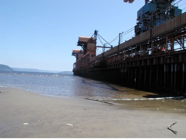
Figure 1 - Wharf during summer (low tide)
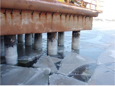
Figure 2 - Wharf during spring thaw (high tide)
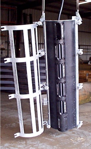
Figure 3 - Pile-mounted anode assembly
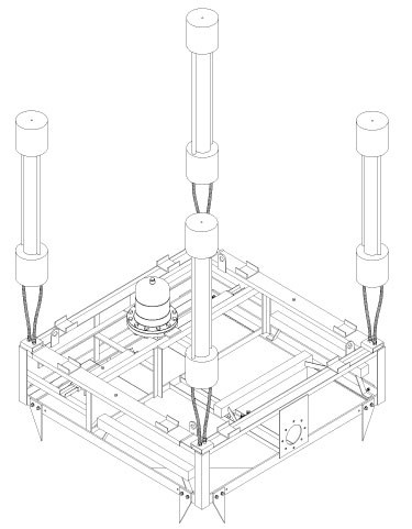
Figure 4 - Buoyant anode assembly
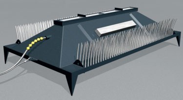
Figure 5 - Vaulted seawater anode assembly.
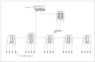
Figure 6 - Typical pile-mounted anode schematic
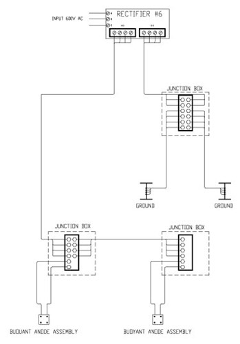
Figure 7 - Typical buoyant anode schematic.
Related content


Technical papers


