Technical Article
The role of cathodic protection in offshore pipeline integrity
by Jim Britton (1998) from Hart's Pipeline Digest
 Download this article
What is out there?
Over 24,000 miles of pipeline have been laid on the Outer Continental Shelf (OCS) in the Gulf of Mexico since 1948. Over the years, much of this pipeline has been abandoned or removed, but as of June 1997, there were still some 17,000 miles of active pipe. Pipe-laying activity has been up and down over the years, somewhat mirroring the "boom and bust" cycles of the oil and gas industry. Some 1,222 miles are over 30 years old, and 5,952 miles have celebrated a 20th anniversary. Obviously these 5,000-plus miles of pipe would be considered at higher risk from an integrity standpoint than the 11,000 miles younger than 20. The mere fact that these old lines are still in operation reflects well on the skills of the corrosion control community (Figure 1).
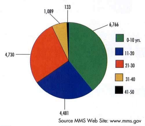
Figure 1 - Active Gulf of Mexico pipelines: Mileage vs age
External corrosion control of offshore pipelines
All offshore pipelines are protected from seawater corrosion in the same way. The primary corrosion control system is pipeline coating. This is supplemented with cathodic protection (CP) to provide protection at coating defects or "holidays." In the Gulf of Mexico, the pipeline coatings used until the early to mid-1970s were either asphaltic/ aggregate, "Somastic"-type, coatings or hot-applied coal tar enamels. Since then, the trend has been to use fusion-bonded epoxy powder coatings. In the earlier days, the trend in cathodic protection (CP) was to rely on impressed-current systems. In the 1960s and early 1970s, zinc bracelet anodes attached to the pipe were widely used. Since then, more efficient aluminum alloys have surpassed zinc as the preferred material for offshore galvanic anodes. There are, however, still some operators using impressed current systems and some using zinc anodes.
Bracelet anodes
Virtually all new pipelines installed in the Gulf of Mexico are equipped with aluminum bracelet anodes. There are two basic types, square shouldered and tapered.
The square-shouldered anodes are typically used on pipe that has a concrete weight coating. When installed, the anodes are flush with, or slightly recessed inside, the outside diameter of the concrete.
The tapered anodes are designed to be installed on pipelines with only a thin film corrosion coating. The whole idea is to protect the bracelet anodes during the pipe-laying process. The anodes are particularly at risk from mechanical damage when the pipeline travels over the stinger on the back of the lay barge.
Even with these tapered designs, non-weight-coated pipelines still sustain anode damage, which can in turn cause coating damage. Several methods are being used to combat this problem. The use of cast-on polyurethane tapers is gaining popularity, and mounting both halves of the bracelet on top of the pipe is a common technique when pipe is laid from a reel barge and the anodes have to be attached offshore (Figures 2 and 3).
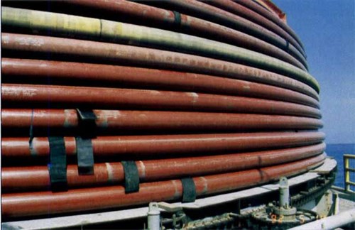
Figure 2 - Six-inch pipe reeled on the barge Chickasaw
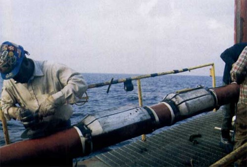
Figure 3 - Tapered bracelet anodes installed on top of pipe
Designing CP systems for offshore pipelines
When designing a cathodic protection system for a pipeline, the corrosion engineer has to consider the following variables, all of which will have an impact on the final anode alloy and size selection:
• Design life required - (minimum is 20 years)
• Pipe diameter length and to-from information
• Geographic location
• Type of coating
• Pipe-lay / installation method
• Water depth
• Burial method
• Product temperature
• Electrical isolation from platforms or other pipelines
The smart cathodic protection designer will look early on at the intended pipe installation method, as this will have a direct impact on the amount of coating damage one may expect (there is also a risk of having anodes detached during the lay process). In all pipeline design guidelines, the conservative approach is advised. For example, the majority of early Gulf of Mexico (buried) pipelines were designed on the basis of 2 mA / ft. of bare steel and 5% coating failure. In essence, this means taking 5% of the total pipeline surface area, and applying 2 rnA / ft. of cathodic protection current to it. This may sound reasonable, until one looks at what 5% bare means:
On a 40 ft. joint of 12 in. pipe, 5% bare coating would have 2 square feet of bare steel, or to express it another way. 4 linear feet of pipe would have the coating gone from 180° of the circumference. This is an extremely conservative figure. As a result, the early pipeline system designs would appear to be very conservative.
Pipeline integrity
When considering the role of cathodic protection (CP) in pipeline integrity we should investigate what causes offshore pipelines to fail and leak. If all the failures of pipelines in the Gulf of Mexico were counted and tabulated, the findings would probably show the general trend expressed in Figures 4 and 5. (These graphs are based on studying a limited sample of failure reports from two oil companies.)
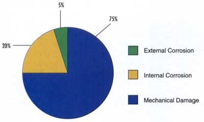
Figure 4 - Causes of offshore pipeline failure
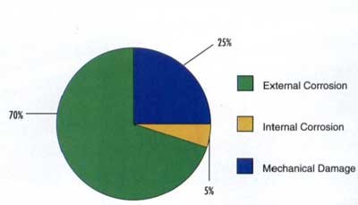
Figure 5 - Causes of offshore riser failure
Since external corrosion is only responsible for a very few of the documented pipeline failures, we could truthfully say that, in general, the combination of CP and coatings is doing a good job.
However, we must not be led into a false sense of security. The only reason the external leaks have not started in earnest is that the old systems were unknowingly over-designed. Thus, a 25-year design life has effectively turned into 30, 35 or even 40 years.
There is a practical limit on how long sacrificial anodes will last, and it is based on the auto-corrosion rate of the anode material. If we were to assume that pipeline systems are all good for at least 30 years, then there should be several thousand miles of pipeline with depleted CP systems (Figure 1). The question, then, is why are we not seeing more external failures?
In truth, the answer to that question is that we probably are seeing a higher external corrosion leak rate than we have at any time in the past. But when will it peak? The pitting rate of steel in seawater on a well-coated pipeline in the absence of cathodic protection anodes could vary between 0.01-0.05 inches per year. Thus, it could take anywhere from 5 to 25 years to pit through an inch of steel. This amount of loss could be sufficient to cause a pipeline failure. Higher corrosion rates can be generally expected when the pipe coating has a combination of large damaged areas and adjacent pinhole defects, and when the pipe is exposed to seawater rather than mud. There is also a particular risk of microbiologically influenced corrosion (MIC) on buried lines with bitumastic-type coatings and depleted cathodic protection.
What is the risk?
On pipelines in excess of 30 years old, the risks are quite high. If the cathodic protection systems have depleted, then corrosion will begin at numerous sites all over the pipeline. Unless detected and retrofitted, the first leak could be the end of the pipeline, as the next several hundred won't be far behind. There are only so many clamps that an operator can afford to install before economic concerns dictate pipeline replacement or abandonment. Given the cost of laying pipelines offshore today, many of the lines will never be replaced, and this could result in early deaths of the oil and gas fields they service. Other old lines are the critical links between the new deep water fields and the shore-based markets. Loss of these lines will present an interesting and unenviable dilemma for operators.
What is the answer?
There are three basic strategies that a pipeline owner can adopt:
1. Survey the pipeline cathodic protection system.
2. Retrofit the cathodic protection anodes on pipelines of a certain vintage.
3. Do nothing (and hope that the laws of electrochemistry will ignore your pipeline), essentially ignoring the problem.
Cathodic protection surveys
Close-interval cathodic protection surveys are the most logical strategy, but strangely enough, operators in the Gulf of Mexico survey very little. When a survey is actually run, it is usually of little value because the method used (trailing wire) inherently produces erroneous data.
There are accurate survey systems available; these either involve physically contacting the line at intervals or utilizing remotely operated vehicles (ROV's) (Figure 6) to track the pipeline and carry reference electrode arrays above the pipeline at known locations (a typical plot from such a survey is shown Figure 7). This type of survey will let the operator see the condition of the line and make informed decisions regarding retrofitting.
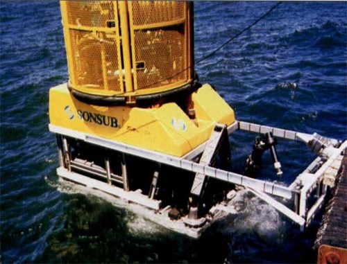
Figure 6 - Work-class ROV Challenger equipped for pipeline survey. Photo courtesy of Sonsub Inc.
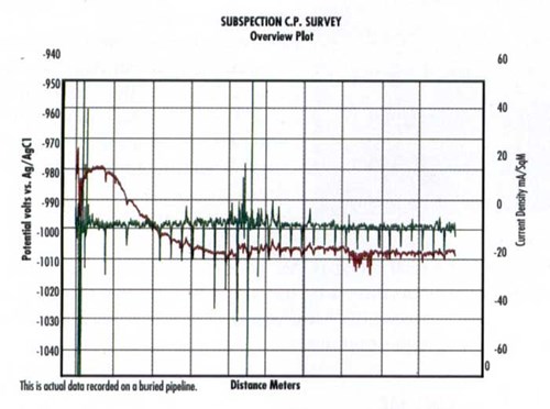
Figure 7 - Detailed pipeline CP inspection plot. Green trace is current density, red trace is potential. Downward green spikes indicate anode locations; upward spikes reflect coating damage.
In addition to the corrosion data shown, the survey will also yield important information on the precise location of the pipeline and the depth of burial below the seabed; these data points can be crucial when designing the eventual anode retrofit.
Retrofit anodes on pipelines of a certain age
Retrofitting the cathodic protection system with supplemental anodes would only make sense if the line in question is very old and the required additional life were significant. The cost to perform a pipeline cathodic protection inspection will run anywhere from $2,000 to $6,000 per mile, and that cost may be eliminated if the decision to retrofit is made. There will only need to be a post-installation survey, once the new anodes are laid.
Of course, retrofitting pipeline cathodic protection systems offshore is not always a simple matter, especially when lines are deeply buried. Often, the retrofit program will need an up-front survey to find the pipeline - so why not survey it first?
Do nothing
Very often this decision is made based on the following logic: "If I know I have a problem, I will have to take care of it; if I don't survey the pipeline, I will not have to find out whether or not I have a problem." This logic sounds like the chronic smoker who dares not visit the doctor for fear it will be discovered he has lung cancer! A surprising number of operators follow this logic.
Summary
In summary, it must be concluded that cathodic protection plays an absolutely vital role in pipeline integrity offshore. Cathodic protection is cheap and reliable, with an outstanding track record of success in offshore applications. But cathodic protection systems have a finite life and unprotected steel has a very short life in seawater. Check your cathodic protection if the pipeline is more than 25 years old.
About the author
Jim Britton has worked in the corrosion control industry since 1972 and has been primarily involved in offshore and marine projects since 1975. He holds a bachelor's degree in corrosion technology from the United Kingdom. His work brought him to the United States in 1982. In 1986, he founded Deepwater Corrosion Services Inc., which specializes in engineering and manufacturing retrofit cathodic protection systems for offshore assets. Britton is a consultant for major oil companies worldwide. He has published a variety of articles and has been a guest lecturer at colleges and universities throughout the US. He has been an active member of NACE International since 1979.
Want to receive an email when Deepwater publishes new corrosion-related technical papers, case studies, and more? Sign up for our Corrosion Newsletter using the form below. You can unsubscribe at any time.
Related content


Technical papers


