Technical Paper
Corrosion protection program for a high-temperature subsea pipeline
by Mike Surkein and Steve LeBlanc, Shannon Richards, John P. LaFontaine (2001)

Abstract
A subsea pipeline has been installed with a novel corrosion protection scheme. The pipeline and associated components have been protected from corrosion with a combination of a high temperature pipeline fusion bonded epoxy coating, a thermal spray aluminum coating and sacrificial cathodic protection anodes. Due to the high operating temperature of the pipeline, anode bracelet installation on the pipeline was not desirable. A cathodic protection attenuation model was used to design the anodes for the pipeline. The model indicated that the sacrificial anodes could be installed at either end of the two-mile pipeline. To assure adequate corrosion control was achieved by the cathodic protection system, a sophisticated in-situ monitoring system was installed. Also, a diver inspection was conducted to measure cathodic protection performance. This paper presents the corrosion control design approach used for each of the major components including the risers, pipeline and buried expansion boxes. The design basis will be compared to the results of the in-situ and diver gathered monitoring data.
Introduction
A typical one-well development for a high-temperature well in shallow water includes a three or four-pile platform, wellhead coolers and utilities. These facilities are required to protect the flowline from the increased corrosion rates and mechanical difficulties that it will experience at full well-stream temperatures. For the development being discussed, wellhead temperatures range from 265 F (129 C) to 315 F (157 C). The challenge of this design was to minimize the wellhead facility by eliminating the cooler and its associated utilities, while addressing the corrosion and mechanical difficulties.
The mechanical design concerns for high-temperature, buried flowlines are thermal expansion and upheaval buckling. Thermal expansion will occur when the flowline operating temperature is higher than its as-installed temperature. In buried environments, natural flowline expansion is constrained by the axial and lateral loads of the soil on the flowline. Where there are imperfections in the flowline profile, the line will tend to experience lateral or upheaval movement.
To overcome the thermal expansion challenges; the flowline was designed with expansion doglegs. The doglegs were housed in expansion boxes (Figure 1). The expansion boxes allowed lateral growth of the flowline.
Corrosion concerns at elevated temperatures include high cathodic protection consumption and coatings degradation. Anodic current density increases and its capacity decreases with increasing temperatures. Both of these conditions work against a standard system of bracelet anodes installed directly onto the flowline. The challenge in selecting a suitable coating is to find a system that stands up to high temperatures and resists cathodic disbondment.
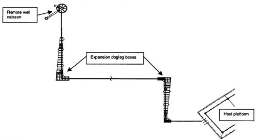
Figure 1 - Simplified diagram of the high temperature flowline
Temperature effects on cathodic protection
In general, corrosion is arrested when the current density on the cathode exceeds the oxygen replenishment rate, according to the equation:
02 + 4e- + 2H2O --> 4(OH)- (1)
This reaction raises the pH at the boundary, and if calcium carbonate concentration in the electrolyte is near the solubility limit, it will precipitate out on the cathode, restricting oxygen diffusion to the cathode, and current density decreases.
Cathodic protection anode consumption increases drastically at the design temperatures of this flowline. The current density required to protect buried bare steel at 77 F is 2 mA/ft2 (1). As temperature increases, the current density requirement increases at a rate of 0. 1 mA/ft2 per 1.8°F increase above 77°F (0.1 mA/m2 as temperature increases above 25 C). Conversely, the anode current capacity decreases as the temperature increases as shown in Figure 2 (2). Since no industry data was found at the design temperatures for this flowline, the anode properties were extrapolated.
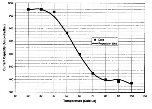
Figure 2 - Effect of temperature on the current capacity of A1-Zn-In anodes in seawater
Corrosion control for the pipeline
Coatings - Corrosion control of marine pipelines is usually achieved through the use of protective coatings and supplemental cathodic protection. When selecting a coating system for a pipeline or structure several considerations must be made including:
1. Effect of cathodic protection
2. Temperature
3. Life
4. Cost
Marine coatings must be suitable for service with cathodic protection. Specifically, they must be resistant to cathodic disbondment. Cathodic disbondment is the destruction of the adhesion between coating and the surface due to cathodic protection. The coating system must be suitable for the service temperature of the pipeline, in this case up to 150 C (300 F). The coating chosen for this application was a dual coat system of fusion-bonded epoxy and chemically modified polypropylene (FBE/CMPP).
Cathodic protection - Several basic designs were considered for providing cathodic protection to this line:
1. Standard bracelet anode mounted directly on the pipeline
2. Impressed current
3. Remote A1-Zn-In anode sleds mounted on the platforms at either end of the flowline
The reduction in anode efficiency due to elevated temperature eliminates the first strategy. Impressed current cathodic protection was feasible, however such a system would require periodic maintenance through the service life of the pipeline. At the anticipated high temperatures, strategy 3 was most appropriate. Using galvanic anodes from a remote location allows the anodes to operate in ambient temperatures where they are most efficient. It also becomes logistically easier than placing anodes on the pipeline itself. Aluminum anodes alloyed with zinc and indium are commonly used for marine applications due to their reliability and high efficiency and potential.
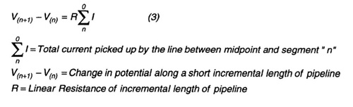
Design - To consider placing the anodes at either end of the flowline, it was essential to conduct a cathodic protection attenuation model of the flowline. The cathodic protection potential attenuation profile of the pipeline, and total current output required from the CP system were calculated based on the following relationships:
V = Ki (2)
V = Change in pipeline potential from native state
i = Applied current density
K = Constant for any temperature
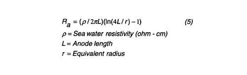
Design procedure - From the attenuation model the total current required was calculated. Assuming (-) 1.00 Volt vs. Ag/AgCl (silver / silver chloride) polarization potential at the end points of the pipeline (drain points for the anode sleds), and (-) 0.800 V at the mid point, a successive iteration solution to this model is valid for a 5% bare surface area. This bare surface or coating breakdown value is considered conservative for a new pipeline. The required current predicted by this model was used to size the anode sleds. Provision was made for the installation of one mixed metal oxide impressed current anode on each sled in case additional current is required. A standard weight/current solution design can be performed to determine anode number and weight for anode sleds at each end of the pipeline. Anode current output is determined by ohm's law:

Anode-to-electrolyte resistance was calculated according to Dwight's equation for long slender standoffs:
A mutual interference factor was used to account for the reduced current output caused by anodes arranged in parallel at close distances:
Anodes must have adequate weight to satisfy the equation:
The anodes were arranged in a sled frame. One frame was mounted on the well caisson and the other was mounted on the production platform (Figure 3.). The sleds were electrically isolated from the structures by placing neoprene underneath the clamps. Continuity with the pipeline was established through a cable jumper.
Figure 3 - Pipeline anode sled
Corrosion control for the pipeline inside the expansion boxes
Coatings - The coating system on the pipeline inside the expansion boxes must meet the same criteria as the rest of the line. Hence, the FBE/CMPP system used on the rest of the pipeline was the coating of choice.
Cathodic protection - The expansion boxes shield the pipeline inside from receiving cathodic protection from the anode sleds. Therefore in the CP design of the pipeline, these segments were assumed to be isolated from the rest of the line. To protect this portion of the pipeline an independent CP system was necessary. Limited accessibility to these locations made galvanic sacrificial anodes the most appropriate option.
Design - The metallic resistance in the pipeline inside the boxes is relatively insignificant. As a result potential attenuation is not a concern. The use of truly remote anodes to avoid the effect of elevated temperature was not viable due to the physical restriction of the box. The best option was to use a composite bracelet anode design (Figure 4). In this approach, the anode segments are actually small standoff anodes arranged radically 4" (10 cm) off the pipe. Offsetting the anodes from the pipe allows the anodes to operate in a reduced temperature environment.
In this elevated temperature environment the current capacity of the anodes is devalued such that anode weight is the limiting design parameter (as opposed to current), hence this design was a weight-based solution. A coating efficiency of 0.9 was used was used for the chosen coating system. This value may be considered conservative but had limited impact on the final system layout.
Figure 4 - Schematic of anode bracelet on the pipeline inside the expansion boxes
Corrosion control for the expansion boxes
Coatings - Thermal spray aluminum (TSA) was chosen as the coating system for the boxes. TSA differs from organic coatings in several areas:
1. It is conductive
2. Higher impact resistance
3. Higher service temperature range
Cathodic protection - The large surface area of the boxes, and the fact that they are electrically isolated from the pipeline make it important to install a separate CP system for the boxes. Flush mounted anodes were selected because their low profile decreased the chance of damage during installation.
Design - The cathodic protection requirements for the inside and outside surface were calculated independently. This approach was necessary because each surface is in a different environment (mud and seawater), and geometric shielding restricts electrochemical communication. A weight-based solution calculation was performed to calculate the quantity of anodes required. As with the pipeline, the design current density and current capacity was adjusted for temperature effects. The coating efficiency factor used for the TSA coating system was 0.9. This number is conservative, as field data on TSA is limited.
Monitoring
In order to verify the performance of the cathodic protection system, an online fixed monitoring system was designed and installed on the pipeline and boxes.
Potential - For cathodic protection to be achieved, the electrochemical potential of steel vs. Ag/AgCl electrode must be more negative than (-) 0.800 volts. The optimum protective potential range is between approximately (-) 0.900 to (-) 1.050 Volts. Reference electrodes are required at several locations to verify protective levels. The location of reference electrodes at the following points were selected:
- On the riser just above the mud line
- Away from the riser in the sand (distance based on thermal gradients)
- Inside the boxes
- On the current density sensors
- Outside surface of the boxes
Current density - Current density monitors (coated/uncoated) were installed on the pipe at the following locations:
- On the risers above the mud line
- On the pipeline just below the mud line
- On the pipeline inside the boxes
These monitors provide additional data that will be valuable in future designs, i.e. the polarization behavior of bare and coated steel at elevated temperatures. Each instrument combines, current density, potential, and temperature measuring capabilities (Figure 5). The CD plates included bare steel, the FBE/CMPP, and TSA coated surfaces. For each set of CD plates there was an Ag/AgC1 reference cell, and temperature probe.

Figure 5 - Schematic of the current density monitor, circa 2001.
Figure 6 - Diver/ROV accessible current measuring boxes, circa 2001.
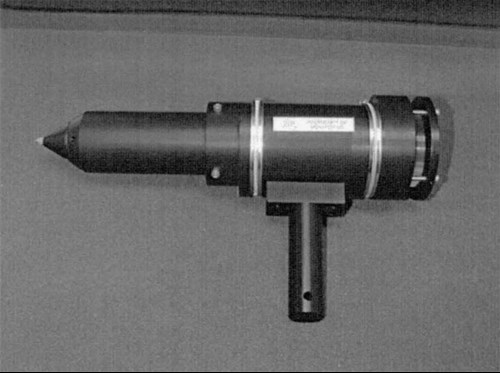
Figure 7 - Self Contained Diver/ROV cathodic protection probe circa 2001
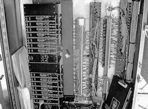
Figure 8 - Remote monitoring data acquisition system
Results
Pipeline polarization - The risers polarized to (-) 1.050 V vs. Ag/AgC1 several days after first oil (Figure 9). Prior to first oil, the potentials were more negative than (-) 1.100 V. The pipeline potentials close to the production platform are more negative than the well caisson side of the pipeline. These results are likely due to temperature effects. The higher temperature on the well side increases current density requirements. The potentials from both the risers and the 1st joint in the mud show the line to be fully polarized. The design potential for these locations is (-) 1.00 V.
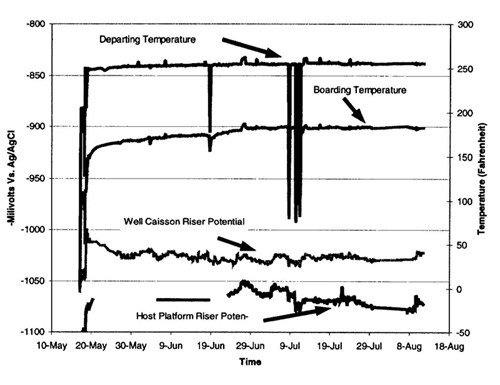
Figure 9 - Riser potentials and temperature during spring-summer 1999
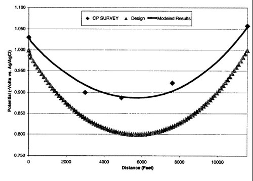
Figure 10 - Potential attenuation models. The graph shows the original design, data from the field survey, and the model based on the actual end point (Riser) potentials
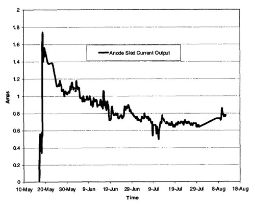
Figure 11 - Well caisson-mounted anode sled current output, spring-summer 1999
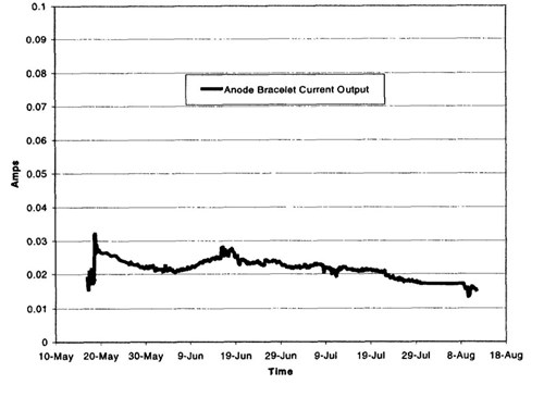
Figure 12 - Anode bracelet current output, spring-summer 1999
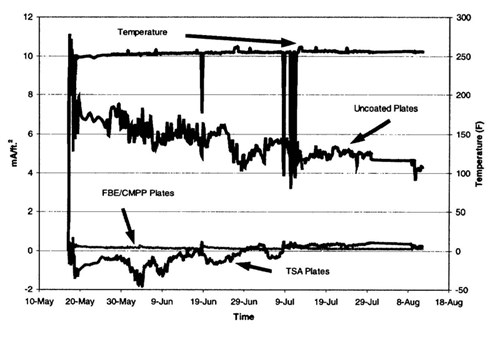
Figure 13 - Current densities on various surfaces on the well caisson riser
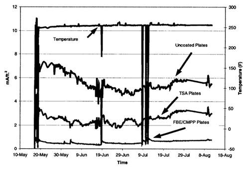
Figure 14 - Current densities on the pipeline inside the expansion box
Conclusions
1. The cathodic protection system is performing well. The pipeline has achieved full polarization and is well protected. The data reviewed to date shows the current required to reach protected levels to be lower than originally calculated. This is new technology however, and should be monitored into the future to assure long-term performance.
2. The CP system is working well inside the boxes. The current output is less than the design parameters. However, data from this area should continue to be analyzed, as current densities are high on the monitored surfaces.
3. The boxes have polarized to design potentials and are well protected.
4. The low current density on the FBE/CMPP coated surfaces indicates that this coating system is performing optimally. TSA coated surfaces in some cases recorded negative current densities indicating anodic properties even when used with cathodic protection.
References
1. Det Norske Veritas, Recommended Practice B401 "Cathodic Protection Design", 1993.
2. Schreiber, C.F. and R.W. Murray, "Effect of Hostile Marine Environments on the A1-Zn-In-Si Sacrificial Anode", paper no. 32 Presented at CORROSION/97, March 1988, St.
Want to receive an email when Deepwater publishes new corrosion-related technical papers, case studies, and more? Sign up for our Corrosion Newsletter using the form below. You can unsubscribe at any time.
Related content


Technical papers


