Technical Paper
Cathodic protection design in deep water: Be safe, not sorry!
by Jim Britton (1999)
 Download this paper
Abstract
Offshore structures in deep water are now quite common. However, a deep water development project still requires significant capital investment on the part of the operator. Corrosion failure is not acceptable. This paper presents a common sense approach to cathodic protection design on deep water projects. Some practical tips for avoiding pitfalls are presented as well as an analysis of the role of ROV's in maintenance and monitoring of these assets.
Introduction
The worldwide development of deep water oil and gas prospects has resulted in the emergence of many alternative schemes and structures designed to produce oil and gas more cost effectively. Early developments used large fixed jacket structures such as the Shell Cognac and Bullwinkle platforms, which are located in water depths of 1000 feet and 1350 feet respectively in the Gulf of Mexico. As drilling moved to even greater depths, these fixed structures were no longer cost effective, and new structure designs emerged: Tension Leg Platforms (TLP's), Floating Production Systems (FPS's), SPAR designs. All of these structures have process facilities located on the surface, above subsea wellheads. The completion of remote subsea wells connected by flow lines and control umbilicals to a surface production facility is now the most common design, being a very cost effective method for developing smaller reservoirs. These remote wells are often several miles from the production facility, and it is not uncommon for several subsea wells to be connected to a single subsea manifold structure, which is in turn connected by pipeline to a production or storage facility on the surface. Cathodic protection (CP) for these wells, manifolds, flow lines, jumpers and umbilicals is the main focus of this paper.
Environmental considerations
Understanding deep water - There are three major factors impacting cathodic protection design in deep water. It is important to understand these factors and how they work together to drive CP designs in this environment:
1. Water temperature - As depth increases, water temperature decreases, and temperature has a direct affect on water resistivity. By affecting the solubility of nutrient salts, lower temperatures change the composition and morphology of calcareous deposits formed at the cathode.
2. Water resistivity - The increase of water resistivity raises the anode to seawater resistance, and this increase in resistance decreases current output from fixed anodes. Water resistivity is therefore a major factor in sizing anodes (rather than using stock sizes) to meet the desired weigh- to-current ratios.
3. Calcareous deposits - These deposits are formed on the cathode surface as a result of electrochemical reactions associated with cathodic protection. This phenomenon is the major contributing factor to why cathodic protection systems work in seawater. The calcareous deposit, acting as a barrier coating, dramatically reduces the current density required for cathodic protection to occur. Calcareous deposits form much slower in cold water, and in general are less dense than deposits formed in warmer waters. Less dense deposits require a higher current density to maintain required cathodic polarization.
In summary, designing deep-water cathodic protection systems requires the following basic design criteria modification:
1. Use higher initial (polarization) and maintenance current density values than would be used in shallow warm water.
2. Use higher seawater resistivity values when computing anode resistance/current output.
3. Use coatings to reduce cathodic protection current requirements.
Cathodic protection design (basic considerations)
Design conservatively - If "conservative" is defined as "being within sensible limits," then we must design deep water cathodic protection systems very conservatively. The cost associated with deep-water oil and gas projects is measured in tens, or even hundreds of millions of dollars. Costs associated with in-situ repairs quickly escalate when there is a problem. For this reason, corrosion failures are not an option. Cathodic protection systems for these pieces of equipment have relative costs in the tens of thousands of dollars. Cathodic protection is relatively cheap; use it wisely. Try to get it right the first time.
Use coatings - As previously stated, cathodic protection design in cold water requires more cathodic protection current per unit area, and in cold water a standard anode geometry will make less current available. It quickly becomes obvious that covering up some surface area with coatings makes a CP design much more manageable. Coatings also provide additional benefits such as increased in-situ visibility, and corrosion protection during onshore fabrication and storage.
Coating efficiency - What is the appropriate coating breakdown-factor to use? This question has been debated among corrosion engineers for decades. Published guidelines vary in their advice on this subject. One prominent code considers some coatings completely worthless after 20 years [1]. The same guideline later provides this statement: "Operator's experience of a specific paint coating system may justify the use of less conservative coating breakdown factors than specified in this document." Clearly conservative common sense must rule. For pipelines, it is common practice to assign a coating breakdown factor of 5% over the design life. For coatings on seawater immersed surfaces near the bottom, we would recommend increasing this numbers to 10-15% initial damage and 20-25% over the design life. This will require more anodes, but remember: be safe, not sorry.
Quality control - It is critical that sacrificial anodes work as designed. Anodes which fail to activate, or which perform with significantly reduced galvanic efficiency could mean that an anode retrofit will be required prematurely. Deep water anode retrofit projects are not impossible, but they are usually very expensive. Anode performance can be guaranteed if the following quality control guidelines are observed:
1. Write a clearly defined specification with special emphasis on electrochemical potential and efficiency testing. Any serious deficiencies in chemical composition will be exposed during these tests. A helpful document has recently been revised by a NACE T7-L technical committee [2].
2. Use an anode alloy with a proven track record. The Al-In-Zn-Si anode alloys are preferable because their behavior in mud environments is more predictable, and because there are less environmental concerns than with Mercury (Hg) or Tin (Sn) activated materials. Aluminum (Al-In-Zn-Si) anodes are more efficient and lighter than zinc anodes and have the highest available open circuit potential.
3. Ensure that the anode specifications require that the testing be performed at the minimum anticipated service temperature.
4. Specify an anode chemistry that will work in cold water and cold saline mud. A suggested modification of an ambient temperature chemical composition versus one intended for cold water is presented in Table 1. This will result in fewer rejects at the testing phase and will reduce the risk of anodes not activating when installed.
5. Ex-pect what you In-spect. Use qualified third party inspectors to assure anode quality.
Table 1
Anode chemistry modification for cold water service
| Element | Typical composition | Cold water composition |
|---|---|---|
| Iron (Fe) | 0.10% max | 0.07% max |
| Zinc (Zn) | 2.8 – 7.0% | 4.75 - 5.25% |
| Copper (Cu) | 0.006% max | 0.005% max |
| Silicon (Si) | 0.20% max | 0.10% max |
| Indium (In) | 0.01 – 0.03% | 0.015% - 0.025% |
| Cadmium (Cd) | Not Specified | 0.002% max |
| Others (each) | 0.02% max | 0.02% max |
| Aluminum (Al) | Remainder | Remainder |
Special considerations for subsea production equipment
The mechanical complexity of a subsea wellhead assembly or a subsea production manifold causes a number of unusual problems for a cathodic protection designer. The wide array of specialized materials used can result in unexpected compatibility issues. It is important to be aware of pitfalls and to design the cathodic protection systems around them. Some problems specific to subsea production equipment are addressed in the following sections.
A. Electrical continuity - Many of the subsea structures currently being installed have hundreds of individual components and many moving parts. A typical subsea wellhead tree is shown below (Figure 1). The anodes for these devices are typically welded to the support frame(s). If all the pieces of the assembly are not electrically connected with a sufficiently low resistance to the frame, then an unbonded component is free to corrode at whatever rate applies to that material in seawater. Some causes of discontinuity are:
1. Coated components joined by bolting. This often results in the fastener and one of the two components being out of circuit with the cathodic protection system. This causes special problems if the fastener is made from a material subject to crevice corrosion.
2. Fluorocarbon (Xylan) coated fasteners that are used because of their predictable torque properties and their limited atmospheric corrosion protection are often left isolated because of the dielectric properties of the coating. Damage to the heads of bolts and nuts from wrenches leaves the fasteners to corrode freely.
3. Necessary articulated joints often results in discontinuities across the articulation mechanism.
4. Mechanical connectors and stabbing posts that may appear to guarantee electrical contact can and have left entire sections of subsea assemblies discontinuous.
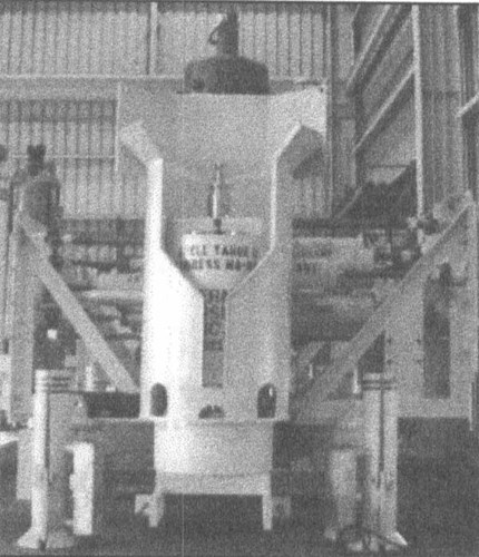
Figure 1 - Typical subsea wellhead assembly
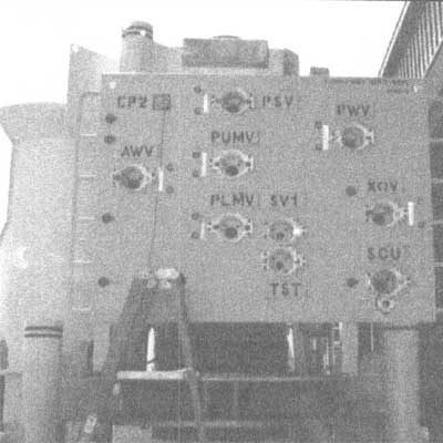
Figure 2 - Cathodic Protection Test Point on Upper Left Corer of Panel
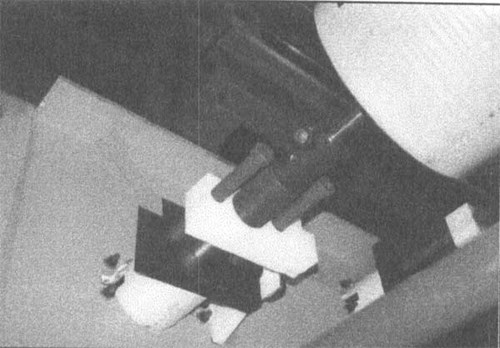
Figure 3 - Typical electrical discontinuity across linkage mechanism
B. Continuity Testing - Most subsea development projects include a phase called System Integration Testing (SIT). All the various components of the system are stacked up or connected on dry land to simulate the completed offshore installation. This is a perfect opportunity to verify electrical continuity throughout the assembly. Continuity is verified from a common test point on the component where the anodes are attached to all other components that comprise the assembly. A standard multi meter can be used to check the resistance, we recommend that a value of 0.3 Ω or less be verified (excluding test lead resistance). The same test points (Figure 2) are used as inspection points for life cycle monitoring of the system. Discontinuities (and there will usually be some) can be fixed onshore quite easily. An example of a typical discontinuity found during an inspection is shown in Figure 3.
Fixing Continuity Problems - Some ways to address continuity problems are:
1. Tack weld across bolted joints.
2. Use stainless steel wire jumpers between components.
3. Use star (serrated) washers under bolt beads.
4. Remove coatings under bolt beads.
5. Use conductive fastener coatings.
6. Locate anodes on more components.
C. Material Incompatibilities - The wide array of materials and corrosion resistant alloys used on these projects can cause problems. It is important to review all materials that will be exposed to cathodic protection for their susceptibility to hydrogen damage at the expected potential. Materials that should be closely checked include: some alloys of titanium, some stainless steels (400 series for example) and 17-4 PH. Sometimes it is difficult to prevent components from receiving cathodic protection even though the material selection engineer may not have intended it.<
D. Cathodic Shielding - The connectors used to make subsea pipeline connections are extremely intricate mechanical devices with tight, flooded interior spaces comprising a large combination of materials. It is important to remember that concentrated areas of uncoated steel (albeit stainless steel) in metallic compartments may be subject to cathodic shielding and may not receive enough current to be adequately protected. Care should be taken to ensure that these areas are provided with anodes inside and outside the compartment. Other areas potentially subject to shielding include components with mechanically attached dielectric buoyancy modules (syntactic foam), these can behave like ultra-thick disbonded coatings. Control pods often have control tubing manifolds under a protective steel cover. These areas must receive special attention from the cathodic protection designer.
E. Mud buried steel - The mud buried steel (pilings, well casings, mud mats anchors etc.) has a surface area which is often an order of magnitude greater than the steel surface in the water zone. In addition to the large area, the surfaces are usually not coated. Even though these areas require significantly lower current densities, the large area can amount to a disproportionately high anode weight requirement, and available anode attachment real estate (areas at which to possibly connect anodes) is usually at a premium. Be sure that these areas are accounted for conservatively and consider the following points and design options when accounting for the mud buried area.
1. Use current attenuation models to calculate how far it would be possible for an anode to "throw" current. Don't account for steel areas below this, because the corrosion rate will usually be minimal. Our designers usually only account for the first 200 feet of pilings and well conductors below the seabed, using a maintenance current density of 20 mA /m2 (2 mA /ft2).
2. Consider the use of sealed thermal sprayed aluminum coatings (TSA) to reduce current requirement. In this case, we suggest using the same current density, still on the first 200 feet, but apply a coating factor of 15% bare.
3. Install attachments on the top of pilings which simplify ROV attachment of cables. With this provision in place, it is relatively simple to install some seabed anode sleds at a remote location to provide the current to these areas and to prevent drain from the close fitted anodes on the subsea equipment. This provision is recommended on all of these types of projects.
4. Don't forget that pilings have an inside too. The top section of pilings normally extend some distance above the pile guide; they are usually bare steel and thus represent a significant percentage of the seawater immersed bare steel area. Don't forget this! Cathodic protection current will be lost to the inside as well as the outside surfaces of these pilings. Coating the upper sections of these pilings is strongly recommended. Sealed TSA coatings will work very well here, and they can be applied to both surfaces.
F. ROV compatibility - At extreme depths >1000 feet, all work on the facilities will have to be performed by a Remotely Operated Vehicle (ROV). These machines, while continually improving, are still machines with limited dexterity and a tether / umbilical. To keep the cathodic protection design ROV friendly, follow these simple steps:
1. Place anodes in areas where they will not interfere with ROV operations, and avoid designs that introduce potential snag points for the ROV umbilical / tether.
2. When placing ROV test points, include a grab rail for the vehicle to hold while monitoring the point. This will reduce wear and tear on the ROV's manipulators and on the monitoring equipment. Figure 2 shows a typical CP test point on a tree (note the grab rail). An ROV stab type current density sensor is shown in Figure 4 (again, note the grab rail).
Figure 4 - ROV stab on a current density sensor - grab rail on left
3. For potential monitoring, provide clearly marked, bare steel test stab locations. The high quality coatings used on many of these facilities do not allow stabbing probes to easily penetrate. Attempting to establish a clean tip contact through a high quality marine epoxy paint could damage the subsea equipment. It also puts tremendous strain on the ROV hydraulic systems.
4. When specifying cathodic protection probes or current probes, select a mount that will easily fit the ROV manipulator and which will require minimum interface to the ROV electronic and fiber optic systems. Figure 5 shows a recently developed self contained deep water CP probe designed for operation at up to 10,000 feet, while requiring no electrical interface to the ROV. A standard tip contact CP probe, which requires surface interfacing, is also shown (Figure 6).
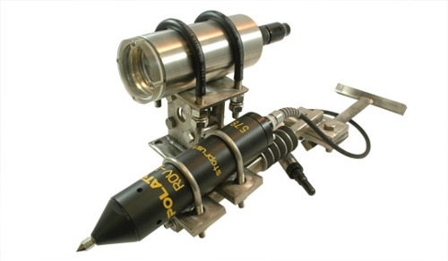
Figure 5 - 10,000 feet rated self-contained CP probe (updated image)

Figure 6 - Standard dual element ROV CP probe (updated image)
Special considerations for deep water pipelines
Q: What is special about a deep water pipeline?
A: Basic design criteria for deep water pipelines and flowlines are not much different from shallow water systems, but there are more risks associated with a pipeline located in deep water. The following suggestions are offered to minimize the risk of problems with these cathodic protection systems. Some of these suggestions would incidentally improve shallow water system reliability also.
A. Anode tapers - Most deepwater pipelines are not stabilized with concrete weight coatings, thus the bracelet anodes commonly used are proud of the pipeline. As a result anodes sometimes detach during the lay process due to the anode snagging on the pipe lay equipment [3][4]. The use of cast polyurethane tapers to anchor the anode and provide a smooth diameter transition has proven to be a very effective remedy to this problem. Placing both anode halves a particular way can also reduce the risk of snagging. One want to be sure that all of the anodes will arrive on the seabed at the six o' clock position. This process is not as favorable as the tapers but may be the only workable solution if anodes have to be attached on the lay barge [5].
B. Pipe lay inspection - The best opportunity to identify and repair problems is always during the installation. Technology is available which will verify that anodes are attached to the pipe and that the coating is not badly damaged before the pipe hits the seabed [5]. In addition, the required post-lay inspection performed by all operators to check the location of the line is also a great opportunity to verify the pipeline's corrosion control system performance. Specify that a cathodic protection probe be attached to the ROV during the post lay (as-built) inspection run.
Cathodic protection testing and monitoring with ROVs
Introduction - Without the ROV there would be no oil and gas development in water depths greater than 1500 feet. These underwater robots are complex machines without brains. We have to make it simple for them to do the work of corrosion technicians [6]. With subsea developments we do not have the luxury of running cables to the surface. Therefore, we must use the ROV. Equipment made especially for ROV's is now available to perform the following tasks:
Electrical potential surveys - A wide range of equipment is available for point and continuous potential surveys on subsea equipment and the associated pipelines.
Current density and anode current measurement - Historically this has been achieved using the electric field gradient method [7]. A newly developed fixed monitoring instrument allows a current density monitor or monitored anode to be deployed for measurement with an ROV (Figure 4). By stabbing a self contained readout into the fixed contacts the voltage drop shunt can be accurately recorded.
Conclusions
When designing a CP system in deep water, be safe, not sorry! Pay close attention to the structure, its continuity, what it's made of, its geometry, and how it will be protected over its life cycle. Be conservative with coating and cathodic protection designs, but make retrofit provisions by providing simple ROV attachment points. Ensure that only quality materials are used in the corrosion control system. And last but not least, hire a corrosion engineer to review all the design specifications, coatings vs. materials vs. cathodic protection.
References
[1] Del Norske Veritas (DnV) - Recommended Practice RP 8401 - "Cathodic Protection Design" - 1993
[2] NACE International- TMOI90-98 - "Impressed Current Test Method for Laboratory Testing of Aluminum Anodes"
[3] CORROSION '97 - Paper 470 - R. H. Winters, A. Holk -"Cathodic Protection Retrofit of an Offshore Pipeline"
[4] CORROSION '93 - Paper 527 - LJ. Rippon et aI. - "Shorting Pipeline and Jacket Cathodic Protection Systems"
[5] Offshore Magazine April 1996 - J. Britton - "Protecting Pipeline Corrosion Control Systems During Pipe Lay"
[6] Underwater Magazine - Fall 98 P. 47 - J. Britton - "An ROY interface for Corrosion Monitoring Equipment"
[7] CORROSION '92 - Paper 422 - J. Britton "Continuous Surveys of Cathodic Protection System Performance on Buried Pipelines in the Gulf of Mexico"
Want to receive an email when Deepwater publishes new corrosion-related technical papers, case studies, and more? Sign up for our Corrosion Newsletter using the form below. You can unsubscribe at any time.
Related Content
Spotlight

Joliet TLP
Project case study: Anode retrofit for the foundation template of a TLWP in Green Canyon
Read more

Technical papers

