TECHNICAL PAPER
Installation of ROV-friendly cathodic protection systems on two deepwater subsea developments
by D.K Flanery, J Britton, K Thompson and P Sandy (2009)

Abstract
Two deepwater subsea production fields, Arnold and Oyster, started producing in 1998 in the Ewing Bank Area of the Gulf of Mexico. The fields contain a total of four subsea wells with wet trees and flow lines back to a fixed platform. Water depths range between 770 feet (235m) and 1,758 feet (536m). During routine surveillance it was noted that some anodes on the well trees and flow lines had excessive depletion. Since the field was undergoing expansion it was decided to supplement the cathodic protection (CP) systems on all the assets to provide an additional 20 years life. This paper describes the CP design and ROV-friendly methodologies used to install 19 anode arrays with 21 clamped tiebacks onto four flow lines and eight subsea components in 73 hours. Details on initial system performance verification will also be presented.
Background information
The Arnold subsea system is located in 1,758 feet (536m) of seawater and comprises three production trees tied back via jumpers to a central pipeline end manifold (PLEM). Two of the trees were installed in 1997 and a new tree was installed in 2007. An electric-hydraulic subsea distribution unit (SDU) controls the field via flying leads. Twin pipe-in-pipe flowlines supply production from the PLEM to the Lobster platform in Ewing Bank 873, approximately 9 miles west. See Figure 1 for a general arrangement of the Arnold field.
The Oyster field, installed in 1997, is located in 1,250 feet (381m) of seawater and comprises one production tree with one jumper leading back to a single pipeline end termination sled (PLET). An electric-hydraulic subsea umbilical termination assembly (UTA) controls these components via flying leads. Twin pipe-in-pipe flowlines supply production from the PLET to the Lobster platform, approximately 3 miles west. See Figure 2 for a general arrangement of the Oyster field.
During an inspection of the Arnold and Oyster electric-hydraulic umbilicals that run between the Lobster platform and the Arnold and Oyster fields, survey personnel noticed apparent excessive depletion of the Arnold trees’ anodes. The field owner decided to investigate why the anodes were depleting prematurely and determine a cost-effective method to extend the life of the CP system.
Analysis of historical data
Based on the time in service, the anodes on some field equipment had greater than expected depletion(1). The most severe anode depletion occurred on the Arnold wellhead trees and Arnold PLEM. During the survey no gross coating failure or mechanical damage was observed on any subsea components. One possible cause for premature anode depletion was unaccounted metallic surface area via adjacent, electrically continuous structures. For example, it is possible the well casings were not considered in the original wellhead tree CP calculations; however, no CP designs were available to confirm or dispute this idea.
Another possible current drain is the sheet piling used to stabilize subsea equipment (e.g. PLEM, UTA, etc.). Sheet piling is attached to seabed structures and driven into the ocean floor to prevent lateral movement. Coating removal may occur during this pile driving thereby creating higher current demand. This cannot be observed for proof as the sheet piling is subterranean.
Limited survey data prevented accurate inventory of subsea equipment(2) affected with prematurely depleting anodes. As was previously stated, the primary goal of the survey was not to evaluate the CP system, but to inspect the umbilicals. Potential measurements were taken on anodes of certain field equipment (i.e. there were no potentials measured on the cathode surface). Original CP design data was limited(3) and did not provide enough information to evaluate CP design performance. The subsea fields were slated for continued service and expansion. Due to the projected remaining life of these fields, lack of information, and the expense of mobilizing a full-scope CP survey, the asset owner decided to supplement the CP systems.
CP system design
The 20-year life extension CP retrofit system comprised 19 anode pods with custom clamps and tie-back cables. Anode pods comprised four each aluminum anodes. These pods were distributed within the Arnold and Oyster fields as well as along their flowlines leading back to the Lobster platform. The Arnold field was retrofitted with five anode pods for the equipment and eight pods evenly spaced along the flowlines. The Oyster system was retrofitted with two anode pods within the equipment field and four pods along the flowlines. CP designs for the field equipment were in accordance with DNV RP B4011 and NACE SP01762 . Flowline CP calculations were in accordance with ISO 15589-23 .
With the exception of those installed in the Oyster field, all anode pods were identical to maximize versatility and to simplify logistics(4). Though anode pods are large, approximately 8 ft. long x by 8 ft. wide x 12 ft high (2.44m x 2.44m x 3.66m), their shape and modular design allowed them to be nested to minimize freight costs. Each pod consisted of four anodes, a structural frame, a ballast concrete mattress, and hardware for tie-back cable connection as seen in Figure 3.
Each clamp was custom-made to match the member or flowline to which it was to be attached. Figure 4 shows a clamp made to attach to a box beam or I-beam member. Multiple factors contributed to the flowline clamp design including: pipe diameter; type(s) of coating(s); coating thickness and depth of burial. For example, thicker coatings, such as polypropylene/polyethylene or thermal insulation, require special electrical contact screws long enough to pierce the coating and safely make contact with the cathode.
For subsea equipment clamps, additional considerations included structural member shape and mechanical interference with adjacent components. The key components of each clamp was a “fishtail” style grab handle, suitable for a wide range of ROV manipulators, an electrical-mechanical contact screw, which also incorporated a fishtail handle, and hardware for tie-back cable connection. For clamps attached to round members and flowlines, spring-loaded cam assemblies were integrated to engage the pipe while the ROV tightened the contact screw.
CP retrofit installation design
1. Pre-mobilization assembly:
Prior to vessel mobilization all clamps, cables and ballast mattresses were assembled to the anode pods, dockside. Clamps and cables were rigged in a ROV-friendly manner (i.e. easily handled or operated by ROV manipulator arms and ROV propulsion) onto cradles located on the side of each pod. For installation coordination and tracking purposes, pods were numbered and recorded. The fully assembled anode pods were then loaded onto the vessel and grouped by installation site.
2. Deployment:
All Arnold and Oyster subsea facilities were retrofitted in 73 hours. Concurrent activities in the field required the CP systems to be installed within windows of opportunity. Due to the flexibility of design, the CP system installation sequence was easily tailored to adapt to these requirements.
Prior to launching any CP materials, the installation target box was surveyed to ensure that the area was free of large debris. Each anode pod required approximately one hour to rig for deployment aboard the vessel, overboard, set in position on the seabed and detach from vessel crane rigging. Rigging for deployment includes connecting the vessel’s crane hook to the anode pod’s pad eye and final inspection by the ROV pilot prior to deployment. Figures 5 and 6 show the anode pod being set in its installation target box and detached from vessel crane rigging.
The vessel on this project had two work class ROVs. Though only one ROV is required for installation of anode pods and clamps, simultaneous operation of both ROVs accomplished the job in less time. For example, while one ROV was connecting a clamp, the other could set the next anode pod.
3. Clamping and testing:
Once the pod was set, an as-found CP potential was taken on the nearby equipment or flowline using a contact CP probe. Potentials for all equipment and flowlines was more negative than (-) 0.800 V with respect to a silver/silver chloride reference electrode. Next, the ROV removed the pre-rigged clamp from the pod and attached it to the target member or flowline. Once firmly attached, the clamp was tested for electrical continuity with the member using the contact CP probe – see Figures 7 and 8.
In addition, the post-retrofit potential was compared to the as-found potential to verify the CP system’s effectiveness. Except for two pod installation sites on the flowlines, post-retrofit potentials shifted more negative than pre-retrofit potentials. It is assumed that potentials shifted positive at two installation sites on the flowlines for the following reasons.
- The flowline was well-coated and well-protected at the pod installation site.
- The anode pod frame was not coated and added enough bare steel to the flowline to cause a slight positive shift in potential (approximately 0.010 V).
- The post-retrofit potentials were taken immediately after anode pod attachment and may not have allowed enough time for polarization of the anode pod frame. This clamping and testing process consumed approximately one hour per pod.
4. Challenges encountered:
A portion of the Arnold flowlines traversed a major seabed escarpment causing both flowlines to become deeply buried. The location of this geographical feature coincided with a proposed anode pod installation site. However, the redundancy of the CP design permitted flexibility in the installation locations. After field attenuation analysis, it was determined that moving the anode pod’s planned location approximately 200 feet down the pipeline would avoid the escarpment and would not impact the effectiveness of the CP system.
The clamp for the Arnold SDU was not large enough for the intended member (during the design phase, scaled drawings of the SDU were not available). Alternatively, the clamp was attached to a padeye located on top of the SDU – see Figure 9. In the event the clamp had not fit any SDU frame component, field modifications could have enlarged the clamping interface without compromising structural integrity or function. Modification of the clamp would require the recovery of the anode pod, tie-back cables and clamp. All deployment steps would have to be reversed to reconnect the pod to the vessel’s crane and recover the anode pod. Once aboard, the clamp would have been mechanically altered using tools commonly found on ROV support vessels. The total time to rework the clamp would have been approximately one hour.
Conclusions
Deepwater subsea equipment and flowlines present a set of challenges different than those of shallower offshore structures. Installation costs for specialty vessels, highly technical equipment and experienced personnel are some of the challenges facing deepwater cathodic protection retrofits. A successful cathodic protection life extension system design should encompass all known historical design and survey data, should be field adaptable to accommodate for unknown factors due to limited information, and should not interfere with the functionality of the structure to which it is connected. Finally, the design should minimize project costs by optimizing the number of installation sites.
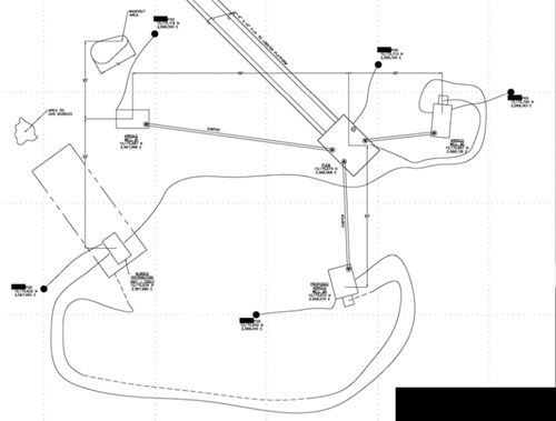
Figure 1 - Arnold Field Layout with anode pods, tie-back cables and clamps
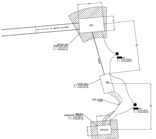
Figure 2 - ROV utilizing SunStation's light-powered readout
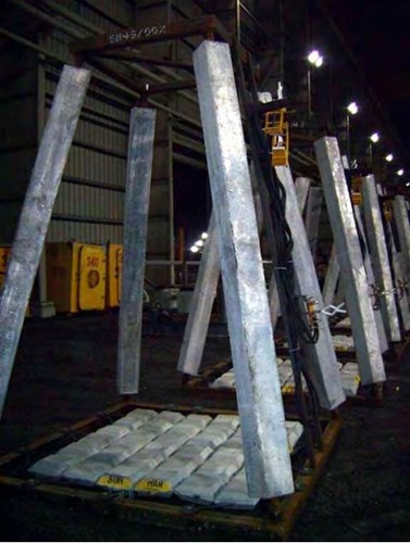
Figure 3 - ROV utilizing SunStation’s light-powered readout
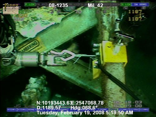
Figure 4 - Custom clamp engaging the member of Oyster umbilical termination assembly
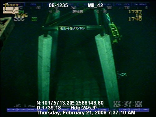
Figure 5 - Anode pod set on seabed
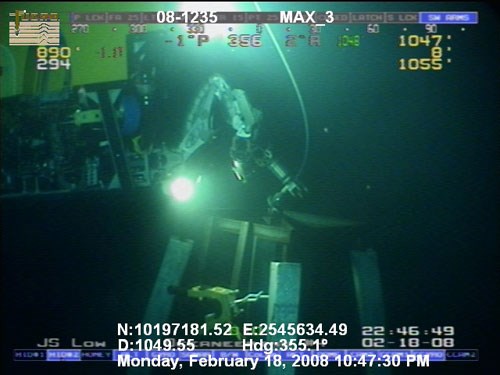
Figure 6 - ROV disconnecting crane rigging from anode pod
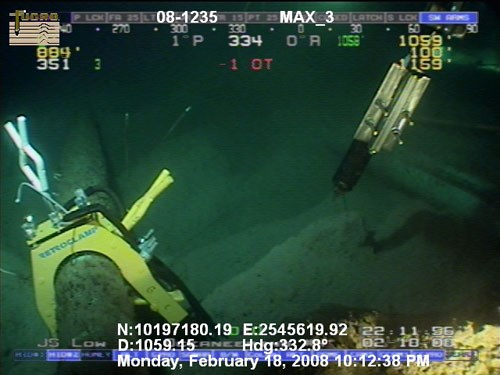
Figure 7 - Clamp connected to flowline; contact probe testing for electrical continuity
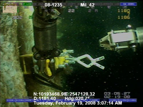
Figure 8 - Clamp engaging the member of a well tree
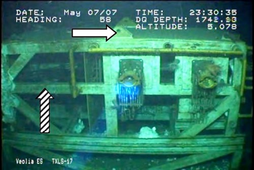
Figure 9 - Intended clamp location (striped arrow); Actual clamp location (solid arrow)
Notes
(1) Anode corrosion product was not removed during this survey. Removal of corrosion product would have facilitated a more accurate quantification of anode consumption.
(2) The original scope of work for this survey did not include cathodic protection. A cursory CP survey was conducted after heavily depleted anodes were discovered on a production well tree.
(3) The only original CP designs available were of the Arnold PLEM, Oyster PLET and both flowline systems.
(4) The anode pods in the Oyster field incorporated hardware for two sets of tie-back cables – each pod provides protection to more than one location.
References
1 DNV-RP-B401, “Cathodic Protection Design” (Høvik, Norway: DNV, 2005).
2 NACE SP0176, “NACE SP-0176-2007 Corrosion Control of Submerged Areas of Permanently Installed Steel Offshore Structures” (Houston, TX: NACE, 2007)
3 ISO 15589-2, “Petroleum and natural gas industries — Cathodic protection of pipeline transportation systems — Part 2: Offshore pipelines” (Geneva, Switzerland: ISO, 2004)
Related content
Spotlight

Arnold / Oyster fields
Project case study: Anode retrofit on two deep-water subsea fields in the Gulf of Mexico
Read more


Technical papers


