Technical Paper
Extending the life of cathodic protection systems for offshore pipelines. Some recently applied new technologies.
by Jim Britton and Dick Baxter (2008)
Abstract
This paper discusses the practicalities of installing replacement cathodic protection to ageing offshore pipelines using diver assisted and diver-less systems. Current technology for condition assessment and life extension design criteria will be discussed in conjunction with new hardware technologies being utilized to improve reliability and reduce cost of life extension projects. The paper will also present some leading edge technology designed to reduce life cycle inspection costs which has been applied to pipeline systems in the USA Gulf of Mexico and Atlantic areas.
Introduction
In essence we are really talking about technologies to facilitate installation of cathodic protection systems subsequent to installation of the steel asset. This is how virtually all onshore systems have always been deployed, first install the pipeline and then install the cathodic protection. Offshore, the trend toward pre-installation (bracelet anodes) was driven by installation methods and economics. When considering a life extension the drivers are the same but the challenges completely different.
Having made the decision that a life extension is required, the key questions when planning an offshore pipeline project of this type are:
“How far apart can I install the new anodes and how much time will I need to spend at each location?”
The answers to these two questions allow the cost of the project to be estimated; the installation is normally at least 75% of the project cost.
“Will I need to use divers or can it be done with an ROV (Remotely Operated Vehicle)?”
This question will normally determined by the local conditions around the subject pipeline, mainly the water depth and extent of burial. From the above we get to the key elements for the CP engineer to consider.
a. How to confidently maximize the spacing between retrofit current sources.
b. How to have the anode system provide the required CP current which will cover this optimized spacing.
c. Ensuring that the installation procedure and hardware design is fit for the subsea conditions and the resources available.
d. How to minimize time for installation of the anode array and connection to the pipeline.
Design considerations
Codes / standards - The most widely used design guidelines (ISO 15589-2: 2004, DNV RP F103) do not specifically address pipeline retrofits. There is than an erroneous reference in the ISO document (section 5.2.5) which suggests “impressed-current systems may be preferred as a retrofit system on pipelines with galvanic anode failures, excessive anode consumption, operation beyond original design life or excessive coating deterioration."
This would lead one to believe that impressed current will “throw” further than galvanic anodes, and thus allow greater distances to be covered. This simply is not the case; the limiting factor is the pipeline linear resistance and resultant attenuation of potential as a function of current. This essentially limits the amount of current that can be drained from the pipeline at any single attachment point (without causing over-protection issues); this current limit does not consider the source of the current. The impressed system does allow better control of the drain point potential, but will not allow significantly more pipe to be protected.
For this reason, impressed current is typically only used if it is already in place, and only to protect the first couple of miles of pipe. Virtually all offshore pipeline life extensions have been completed using sacrificial anodes.
Our design philosophy - Neither of the referenced codes offers any real guidance as to how to design a retrofit cathodic protection system, what current density to use, how to take into account the effects of the existing anodes on the pipeline, etc. Both standards list coating breakdown factors for limited numbers of coating systems. The ISO standard being the more conservative of the two. In the absence of specific survey data, or instructions from the client, this is the number that we typically use (more info).
For this reason we have elected to take a conservative approach and design the pipeline life extension system assuming no contribution from the existing anodes. Indeed we assume that all the existing anode bracelets have depleted, leaving connected anode steel core structure as additional coating defects on the pipeline. The coating breakdown factors we apply are based on regional experience from direct assessments, pipeline surveys, and previous retrofit projects, this being in accordance with the code recommendations. Average current density is estimated as (maintenance or mean) level for calculation of potential attenuation.
Anode array design criteria - Over the last several years we have developed a series of standard retrofit arrays that have been attached to pipelines; the three most commonly used are shown graphically [Figs. 1 - 3].
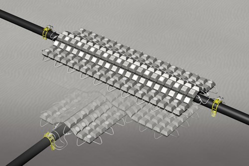
Figure 1 - Anode mat - pipeline retrofit array
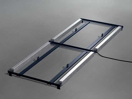
Figure 2 - Rigid sub-bottom anode sled array
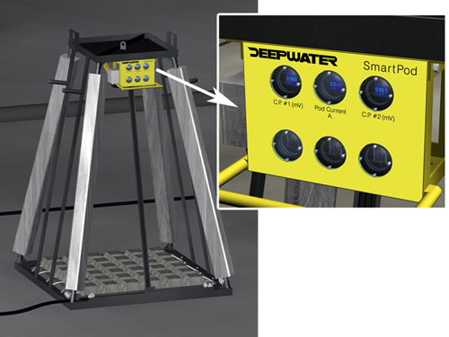
Figure 3 - Deep water monitored anode pod array
We have found good correlation between the Dwight equations [Dwight Reference] and actual performance as measured on complex ICCP anode arrays in seawater; our standard sled and pod geometries utilize these formulae. For our embedded mat anode we used test tank simulations to arrive at the correct resistance equation and known parallel anode arrays were used as calibrators. [Fig. 4] It is important to design sacrificial anode arrays considering the following.
a. Geometric or weight limitations for shipping and handling onshore and offshore.
b. Array and design anode shapes so as to maximize utilization and minimize mutual interference.
c. Ensure structurally compliant construction for offshore lifting and bottom stability.
d. Provide sufficient current per sled to cover all or half of the design spacing / current requirement.
e. If the pipeline is in deep water, design anode array to operate in seawater rather than below the mud line.
f. If operating the anode in the mud, de-rate the alloy capacity by at least 10%.
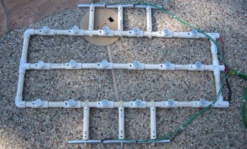
Figure 4 - Anode mat simulator – Note outrigger parallel anode arrays used to reference to Dwight resistance equations for standard sleds. Buttons simulate mat anode elements.
Determination of anode array spacing along pipeline
With all this information, we use industry proven attenuation models [1] to predict the required mid point potential at the end of the life extension. This will of course yield a conservative design since a working offshore pipeline should never be allowed to depolarize completely. A typical attenuation calculation is shown in Attachment 1.
This MathCad file is set up to allow the operator to select the lowest end of life mid point potential that he feels comfortable with (that meets his local regulations). Derivation of pipeline constant and other off-line sections are left out for brevity. The author may be contacted for a full working copy of the file.
Certain enhancements to methodology presented in ISO 15589-2 2004 Section A.10 are evident. It is not the intention of this paper to compare our methods, more to present the methods that we are applying in real retrofit situations (adhering as closely as possible to the code recommendations where they exist). It is noteworthy that our approach ignores the drain point potential spike which is caused largely by sled-induced potential gradients; this attenuates very quickly and may be ignored for the purposes of ultimate distance (anode spacing) calculation.
Retrofit of opportunity - Not every pipeline retrofit project addresses the entire line segment in a single project. Very often anodes are added because there is an opportunity to do so on the back of another activity requiring the pipeline to be accessed, and activities may include secondary construction, repair or maintenance. One example of this is the incorporation of an anode array into a concrete stabilization mattress, which allows the operator to leverage cost of crossing stabilization construction to supplement the CP on a long section of his pipeline. [Fig. 5]
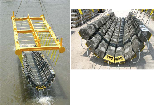
Figure 5 - Shows anode mat construction and typical installation frame.
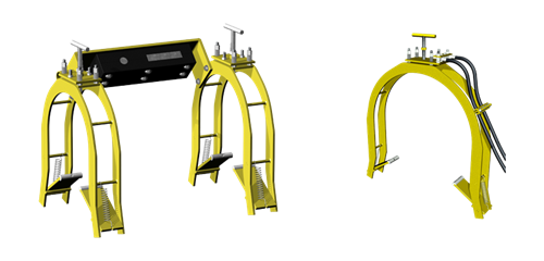
Figure 6 - Clamps used on all retrofits shown left as reference electrode mount.
The anode connection - This is without doubt a critical part of the system. If we cannot electrically connect the anodes to the pipeline, we cannot achieve cathodic protection. We have considered all available methods including wet welding and friction welding, but we keep coming back to the mechanical clamp because a) it's easy b) cost effective and c) well proven. The clamp design we are using is just as easy for an ROV to install as it is for a diver. The clamp has been successfully installed on a wide range of pipelines and risers and is often used to support monitoring sensors. [Fig. 6].
Clamp key design features are:
a) U-Frame – require access to the target from only one direction. This is of particular importance when working with buried pipelines which require excavation to access. Also critical for simplified global ROV integration.
b) Floating plate constant tension system overcomes thermal cycling and creep issues. Important on elevated temperature or thermally insulated systems.
c) Positive lock flappers allow single action installation. ROV critical. Clamp resistance is below 0.05 Ohm. We have typically used 2 x 4 AWG (108 mm2) flexible copper conductors with a suitable insulation material to ground the clamp to the anode array. We have normally used cables 8-10 meters long. This package is provided with additional redundancy by installing 2 clamps per anode array.
The clamp has been used successfully on concrete weight coated pipelines; a cutting tip is used to drill the concrete. This activity should not be attempted until divers / ROV pilots have demonstrated knowledge of the installation procedure accompanying this type of installation. Whenever connecting to a pipeline we have recommended the use of the reader system. This system allows simple verification of clamp contact by monitoring the potential of the clamp during installation. The clamp potential is artificially depressed by attachment of a small magnesium button. Thus when pipeline contact is achieved a large > (+) 100 mV potential shift is indicated instantly. The contact established then the required torque can be applied to the floating plate system. [Fig 7.]
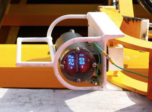
Figure 7 - Reader attached to clamp to verify pipeline contact
Surveillance and monitoring
The use of ROVs to perform close interval offshore cathodic protection surveys will one day be viewed with fond memories, that day is approaching fast driven by economics and the emergence of a better way. Many hours have been wasted comparing one method to another, when in fact none of them is of very much use to anybody. Two emerging technologies will lead the way over the next phase of offshore infrastructure development. Pipelines will be inspected with current monitoring pigs [2] if they are candidate for the method. Permanent point monitors interrogating fixed sensors and sending the information to a point of easy access by an ROV, AUV, and Diver and eventually posted to www. This will be standard operating procedure for pipeline external corrosion monitoring moving forward.
Many subsea locations on pipelines are subject to periodic inspection requirements (Risers, Valve Stations, Dynamic Hang Offs, Subsea Isolators etc.) These locations are usually good candidate locations for permanent direct read CP evaluation stations.
These highly accurate, stable and repeatable data points can be used to confidently assess status of large representative areas, and offer the opportunity to eliminate the need for expensive ROV based CP surveys. This is only possible because the data points gathered from fixed instrumentation which is intimate to the pipeline and displayed on self-contained integral voltage measurement/displays [3]. Once the real long term stability of these systems can be demonstrated, surveillance intensity can abate. Some of these light activated direct read systems are shown [Fig. 8]. They have also been integrated directly into the anode retrofit hardware [Fig. 9]
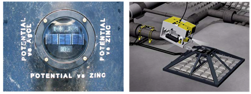
Figure 8 - Seabed deployed monitoring station – light powered readout detail on left
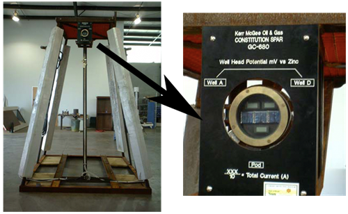
Figure 9 - Anode pod with integral light-powered monitoring system
Case histories
Table [1] shows comparative data on the four projects listed below. Some images of each project are also presented.
1. Northern North Sea – Infield Pipelines
2. Gulf Of Mexico – Deepwater Flow lines and Associated Subsea Trees
3. Gulf of Mexico – Buried Shelf Oil Pipeline
4. Gulf Of Mexico – Deepwater Production Risers
Two recent permanent monitoring retrofit projects using light powered subsea readouts. These projects both involved retrofitting of permanent sensors to the pipelines. Images and graphics of the installations are presented.
5. Atlantic – Buried LNG Pipeline
6. Gulf Of Mexico – SCR Risers
Table 1.
Comparative information on 4 pipeline CP Retrofit projects
| Project Location |
Water Depth (M) |
Facilities | Anode Arrays | Number of Connections |
ROV/Divers/Vessel | Average Time / Array |
|---|---|---|---|---|---|---|
|
NNS
|
150
|
Infield Pipelines CWC
Some excavation |
10 Pods - 7 Rigid
Sleds |
34
|
ROV - 2 x Triton Work
Class 1 x Sea-Eye Insp. Class - Full DP RSV |
14 Hrs
|
|
GOM
|
530
|
Deepwater Flow lines 4
between 5 - 15 km 8 pieces of interconnected subsea hardware. |
19 Pods
|
38
|
ROV - 2 x Work Class
Full DP RSV |
4 Hrs
|
|
GOM
|
20 - 75
|
Offshore gathering line.
Buried CWC all locations |
14 Rigid Sleds at
average 3.6 Km spacing |
28
|
Divers - 4-Point DSV
|
12 Hrs
|
|
GOM
|
1515
|
8 x Deepwater Production
Risers and Subsea |
4 Instrumented
Pods |
8
|
Single WC ROV
Full DP RSV |
8 Hrs
|
Project gallery
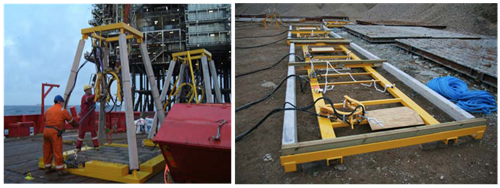
Figure 10 - Northern North Sea – Pod Structures (Left) – Sled Structures (Right)
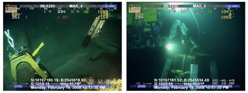
Figure 11 - Deepwater flow lines – Gulf Of Mexico clamp on F/Line (left) & ROV de-rigging (right)
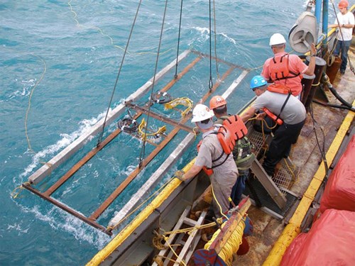
Figure 12 - Gulf of Mexico shelf - typical rigid sled / clamps being over-boarded
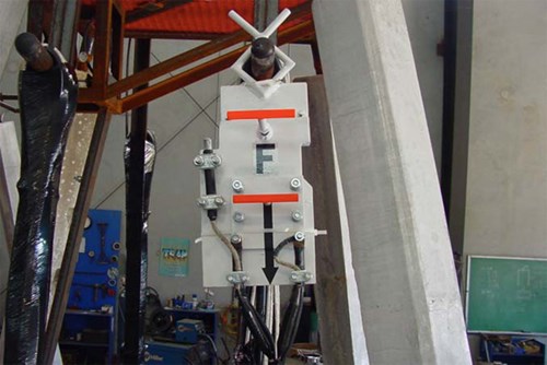
Figure 13 - Monitored pod – Deep gulf shows modified contact clamp
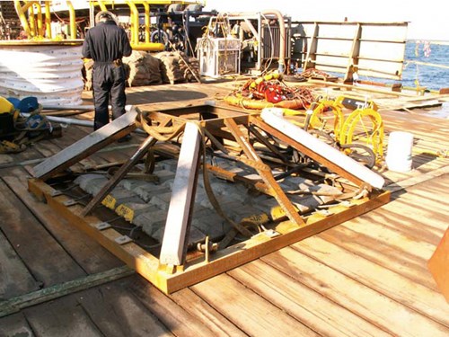
Figure 14 - North Atlantic – Seabed monitoring station reference electrode / clamps in background
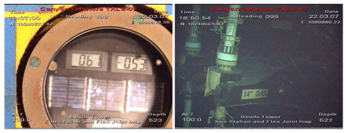
Figure 15 - Anode pod with integral light-powered monitoring system
Want to receive an email when Deepwater publishes new corrosion-related technical papers, case studies, and more? Sign up for our Corrosion Newsletter using the form below. You can unsubscribe at any time.
Related content


Technical papers


