Technical Paper
Corrosion monitoring equipment for ROV interfacing
by Jim Britton (1999) from UI New Orleans

Abstract
Many of the new deep water production fields are beyond the depth suitable for divers, leaving the ROV as the only viable option for performing inspection tasks. This fact has caused new inspection techniques and new equipment to be developed to meet the challenges. This paper describes and documents some of these new techniques and the equipment used.
Types of inspection
The main types of inspection which are performed by ROV's are: visual, cathodic protection level surveys (CP) and ultrasonic inspections (UT). The cathodic protection survey - in conjunction with a visual inspection - is the most widely used for subsea equipment corrosion monitoring. This paper will focus on using ROV's to perform meaningful, accurate cathodic protection surveys.
Types of cathodic protection systems
The vast majority of deepwater subsea production equipment is protected by galvanic anodes (usually aluminum alloy) and coatings. Also, many components on these structures are made from corrosion resistant alloys (CRA's). In order to verify that a cathodic proteciton (CP) system and a coating system are providing adequate corrosion control, it is necessary to take some electrical measurements, which can confirm that the steel components are not corroding in the seawater. These measurements are commonly called cathodic protection potentials or "CP potentials."
Basic potential measurement - A potential measurement is like any other electrical voltage measurement. It is achieved by making an electrical contact to the protected structure and another connection to a device called a reference electrode. For the potential measurement, one simply compares the two. The reference electrode most commonly used in offshore work is the saturated Silver - Silver Chloride cell (Ag/AgCl). This cell couples a pure silver wire with a saturated solution of its chloride salt. When this couple is exposed to sea water a very repeatable voltage is produced. This known repeatable voltage is compared against the unknown voltage of the steel in sea water. The Ag/AgCl electrode is understandably referred to as the "reference electrode."
Unprotected carbon steel (no anodes attached), will exhibit a potential of approximately (-) 0.570 - (-) 0.620 Volts vs Ag/AgCI. When anodes are added the potential will shift in the negative direction; the greater the shift, the more protection is being provided. The accepted minimum potential level required on steel in seawater is (-)0.800 Volts vs Ag/AgCI to ensure full cathodic protection. However a more practical minimum is (-)0.850 Volts. To go even further, most operators would consider the cathodic protection (CP) design of a system inadequate if minimum potentials of (-)0.950 Volts vs Ag/AgCI were not achieved.
A schematic diagram of a steel to seawater potential measurement is shown in Figure 1. The ground connection can be made above water if there is any above-water structure and if it is electrically continuous with the subsea structure:
CAUTION: Some TLP and other FPS designs deliberately isolate tendons and or risers from the floating section of the facility. Similarly, flexible sections of pipelines cannot always be guaranteed to be electrically continuous.
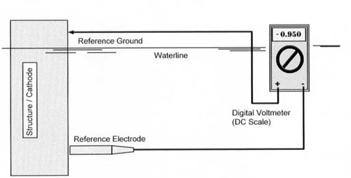
Figure 1 - Structure to Sea Water Potential Measurement Schematic
Subsea completions
Obviously when dealing with a subsea tree or manifold structure, there is nothing above water to be able to hook a reference ground to. For this reason, the ROV cathodic protection probe was developed (see Figure 2). This probe can be interfaced to the ROV in many ways, the most commonof which is to attach it to a multi-function manipulator. Three conductors are then needed in the ROV umbilical, in order to connect the probe to a topside readout: a twisted shielded pair (for the two reference electrodes) and a ground wire (for the tip). These conductors must run all the way to the surface where they can be interfaced to a voltmeter display or into the video writer A-D converter. To complete the survey successfully, the ROV operator must simply "stab" the item under investigation and read the potential. The second electrode in the probe provides an on-line calibration facility to ensure that the readings taken are accurate.
Probe features - When selecting an ROV probe, look for the following features to ensure that the device will give accurate, repeatable measurements and will not cause unnecessary system downtime:
• Rugged construction - The probe will be subject to a lot of abuse, the probe body should be made from a very resilient non metallic material (Delrin works well).
• Twin electrode elements - A single electrode probe cannot be calibrated subsea. If the ROV is recovered after an 18 hour dive and the probe does not calibrate, then all data is unreliable, and the survey will have to be repeated. Twin elements allow continuous, on-line calibration.
• Small replaceable tip contact - The size is important; a large tip will cause a local drain at the contact point and will give false readings. The total area of the tip should not exceed 1 sq. inch. Also, the tip should not be too hard or it will fracture.
• Quality connector - A good quality underwater connector is required; any leakage and the reading will be invalid.
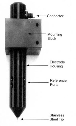
Figure 2 - ROV Tip Contact Probe circa 1999
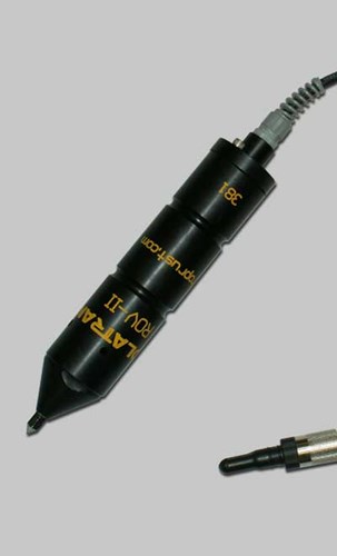
Figure 2A - Picture of updated probe circa 2008
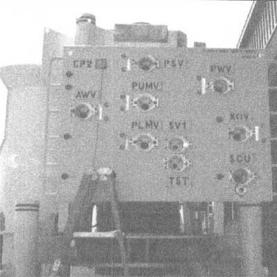
Figure 3 - Cathodic protection test point - upper left panel
Monitoring points - Because a subsea tree is a relatively small piece of hardware (compared, say, to a large platform), it is only necessary to measure a few cathodic protection potentials at key locations. These locations should be located at points the ROV can access easily and on each major sub-assembly of the subsea system. Figure 3 shows a typical cathodic protection test point, which has been left intentionally bare on a subsea tree ROV control panel. These bare spots work well because they negate having to stab through thick coatings; this obviously damages the coating and puts undue strain on the manipulator arm.
These points also provide one additional benefit: they are used during systems integration testing (S.I.T.) to verify electrical continuity between components.
Flowlines and pipelines
Flowlines and pipelines cause an interesting problem for cathodic protection survey. Often in deep water work there is no place to establish a topside reference ground, and even if there were, it would be of little use to us 10 - 20 miles away along the pipeline. We therefore must use a survey technique called the "multi-electrode survey". There are several types. These methods rely on a concept called the "remote potential." The theory behind the remote potential states that if a reference electrode is located far enough away from the structure being surveyed, the potential indicated will be the same no matter where the electrode is located. When this happens, the electrode is said to be at a "remote" location. This is typically no more than 20-30 feet away in seawater, but the further the better. The remote electrode is calibrated to a regular close potential (taken with a tip contact probe, usually on an anode), and then the survey proceeds by comparing the close versus remote cells. Figure 4 shows simply how a 2 electrode remote survey works.
The advantage of this method is that continuous potential profiles can be measured with only periodic contact to the pipe being required for re-calibration of "remote" potential.
Two vs three electrode method - The addition of a third electrode, allows an additional value to be recorded, called the electrical field gradient. This measurement is indicative of the local electrolytic activity around the pipeline. It is useful in predicting remaining life or potential problems. Because of the very small voltages involved, the three-electrode method does require a computer subsea on the ROV. For this reason, the two-electrode survey shown in Figure 4 is more common for most pipeline surveys.
Figures 5 shows a finished survey plot using the three-electrode method. As can be seen, the three electrode survey shows current density, which can give a complete picture of the pipeline cathodic protection / coatings system. Figure 6 shows a typical ROV set up to run a 3 electrode survey.
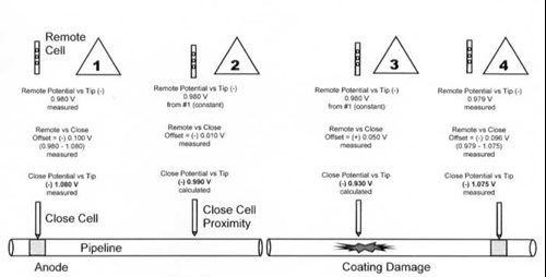
Figure 4 - Schematic representation of remote cell CP survey
Two electrode technique - In figure 4, above the sequence is:
1. The ROV mounted tip contact probe is stabbed to an anode. Three voltages are recorded:
a) the close potential - the actual potential of the pipe at the anode
b) the remote potential - read between the remote cell (deployed over the side of the ship or rig) and the tip making contact with the pipe.
c) the offset - a reading between the close and remote cells. In this set up the following equation will always be true b - a = c or remote minus close equals offset.
2. Now the ROV is flying the line holding the close cell as close to the line as possible but not in contact. The operator can still measure the offset value (c). As the remote potential (b) doesn't change significantly with distance along the line, the operator can calculate the close potential (a), which is the measurement that he/she is really interested in.
3. The ROV is still flying the line, but now over a coating defect. Under normal circumstances one would expect such a defect to cause the pipe potential to fall off, so, still measuring the offset, the operator notes a polarity shift. Applying the same equation, we see that the potential at the defect is less negative than the remote potential. These values would still be detectable even if the pipe were buried, providing that the electrode was directly over the pipeline, above the seabed.
4. The ROV is stopped at an anode some distance (2-3 miles) along the pipeline, and the remote ground is recalibrated. A slight change in the remote ground potential is noted, but this will not normally vary by more than a millivolt or two per mile. The new remote will be used to compute close potential until the next calibration stab.
So, by logging just the offset potential as the line is flown and then adding the remote potential, an accurate profile of the close potential can be generated. An example plot is shown in Figure 7. In this way, anode sites are easily detectable but there is no way of knowing how hard they are working. For most post-lay surveys, this is sufficiently detailed information.
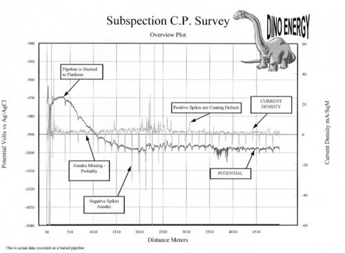
Figure 5 - Typical three electrode pipeline survey plot
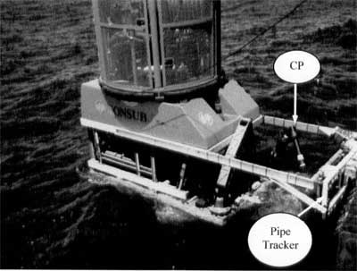
Figure 6 - Challenger ROV rigged for 3 eectrode buried pipeline survey (Photo courtesy SONSUB Inc.)
New developments
A comparatively recent development for deep water ROVs is the move to fiber optic rather than copper cables, wherever possible, for umbilical construction. The advantages in weight and speed are obvious. Another relatively new development is the "subsea toolbox" concept that will have large work class ROVs deployed subsea on protracted dives, with access to all the tools they may need in a rack mounted to the side of the production equipment or on the tether management system.
Deep water probe - This led to the development of a deep-water version of an old tool, the bathycorrometer. A bathycorrometer is essentially a self-contained cathodic protection measurement device which contains the reference ground tip, the reference electrodes and the voltage readouts all in one instrument (see Figure 7). The new bathycorrometer-style device can be placed on the ROV, with no umbilical interface necessary.
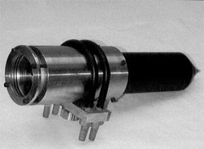
Figure 7 - Typical three electrode pipeline survey plot
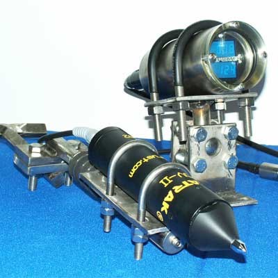
Figure 7A - Picture of updated probe circa 2008
The advantages of this new probe-and-readout system are:
• Ease of interfacing - No umbilical cable spaceis required.
• Twin voltmeter displays and reference electrode elements provide simplest of all calibrations - If both meters read the same, everything is OK. If not, note both readings and compensate on next recovery.
• The display unit has ultra-low power consumption, and light activated sensors only power up when ROV lights illuminate the face plate. These probes can survive subsea for several months.
• No cathodic protection expert is required to oversee the survey offshore. The unit is self explanatory and user friendly.
The unit pictured has a depth rating of 10,000 feet and has recently completed successful trials in the deep water Gulf of Mexico. One disadvantage of the bathycorrometer is its inability to perform remote electrode surveys. This is a development currently under study by the writer's organization.
Old flops
Just to prove that the corrosion community doesn't always get it right, let me mention a couple of the more notable failures in ROV interfaced corrosion monitoring.
Field gradient scanner - The field gradient scanner head was intended to work on platforms to provide multi-directional field gradients and potential information. While conceptually it was sound, practically the difficulty of ROV mounting and accuracy of flying in a platform geometry made the system's data output somewhat difficult to interpret. The system was discontinued in 1988. A picture of the scan head is shown in Figure 8.
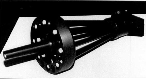
Figure 8 - ROV interfaced field gradient probe had four radial field gradient pairs and a "Snout" proximity electrode circa 1988.
Clip-on ammeter - While divers had moderately good success with clip on ammeters, designed to measure current output from an anode, ROVs just couldn't seem to get it right. The problem was that the clips were very flimsy and the ROV pilots were still on a dexterity learning curve. Attempts to make it work were eventually abandoned. Unfortunately, no image of these ill-fated devices was recorded by anyone from our organization.
A new survey method has been developed which will negate the need for such devices in the future 1.
References
1. J. Britton. "Cathodic Protection Surveys Of Offshore Platforms - A New Approach" CORROSION/98 San Diego, CA. National Association Of Corrosion Engineers
Want to receive an email when Deepwater publishes new corrosion-related technical papers, case studies, and more? Sign up for our Corrosion Newsletter using the form below. You can unsubscribe at any time.
Related content
Spotlight

Shenzi subsea tree
Project case study: SunStation CP monitoring system interrogated by ROV at 4,300 ft
Read more


Technical papers


