Technical Paper
Cathodic protection strategies for FPSOs
by Jim Britton (2002)
Abstract
FPSO (Floating Production Storage and Offloading) structures present some interesting cathodic protection challenges. Are they ships or floating production platforms? Is impressed current cathodic protection the way to go? How do we handle protecting the ballast tanks? What about the mooring systems? Can the cathodic protection systems that we install last 25 years without dry dock maintenance? These and a number of other questions are addressed.
Introduction
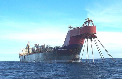
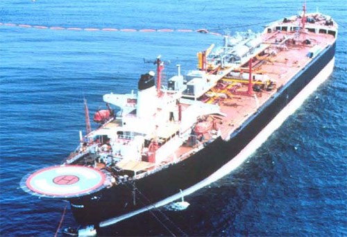
FPSOs generally fall into two categories: New-build vessels and conversions. There is no doubt, however, in either case that the end result still looks like a ship (Figures 1 and 2 below). When considering cathodic protection strategy, however, design concerns have little to do with classifying the asset by appearance. Rather, operability and longevity (for the intended life cycle) are the chief concerns.
Figure 1 - Typical FPSO - Turret moored
Figure 2 - Typical FPSO - Spread moored
The shipping industry is comfortable with ICCP (impressed current cathodic protection) systems for the hull. This reasoning is well justified when one considers the operation and function of a tanker, for example. Impressed current systems offer a number of advantages for these vessels:
1. The low profile of impressed current hull anodes reduces drag and saves fuel, ultimately reducing operating costs.
2. The small number of anode sites required for a hull ICCP system makes dry dock maintenance relatively straightforward. This also reduces the amount of welding required on the hull exterior.
3. ICCP hull systems can be controlled according to cathodic protection potential, optimizing system performance in various geographical areas, particularly when the ship moves from seawater to brackish or river-water conditions.
4. The systems are fairly standard and ship builders are quite familiar with them. This does lower initial installed cost.
5. Classing agencies are very familiar with systems, and they have pre-approved many designs.
The operation and function of an FPSO varies significantly from an ocean-going tanker in the following areas:
1. It is moored in one offshore location for protracted periods of time.
2. Regular dry-docking is not possible.
3. There are a number of appurtenances, risers, umbilical, mooring lines and turret structures that may be in close proximity to the hull.
These differences should be considered when developing a long-term cathodic protection strategy. Certain implications of these differences might prove to make the use of sacrificial anode systems more attractive to many cathodic protection designers.
Comparison of different hull systems
Overview of corrosion control
Coatings - As with many other offshore structures, the primary corrosion control method is the coating applied to the hull. This "front-line" is backed up by a cathodic protection system that takes care of exposed steel at coating defects. When designing the cathodic protection system, it is necessary to predict how efficient the coating system will be initially, and also at the end of its life. Given that regular ocean-going vessels are required to be dry-docked at intervals not exceeding 5 years, there is always an opportunity to repair or re-coat the hull during the ships life, thus the coating degradation has only to be considered over this time span. An FPSO may be offshore for 15+ years. This will require a re-evaluation of the coating performance at the end of this period, and the cathodic protection system will have to be beefed up by some degree to deal with the increased bare steel area that will exist over the long life of the coating system.
Special attention must be paid to the compatibility of the coating system with cathodic protection, this is particularly true of impressed current systems that will generate higher negative potential values at the edges of the dielectric shields associated with hull-mounted anodes.
Impressed Current Cathodic Protection - Many vessels that are candidates for conversion to FPSO service are fitted with hull-mounted impressed current systems. For this reason most operators want to use the same system to protect the vessel in it's new role. If this is the proposed strategy, the following areas must be carefully considered to avoid problems later on in the life.
Control Electrode Location - The control reference electrode(s) monitor the potential of the hull at the area where they are located. This signal is monitored by the controller built into the transformer rectifier power supply. The output current supplied from the anode systems is perpetually adjusted to maintain the potential of the hull (within an acceptable range). On a regular ship system, electrodes will usually be somewhat close to the anode locations (Fig. 3 below). This site selection is based on the desire to minimize the risk of coating damage at areas where the potential is expected to be more negative. When other subsea structures are introduced, particularly turret structures and risers, two problems can (and frequently do) arise;
1. Due to the intricate nature of the turret structure (Fig. 4 below) and the risers that pass through it, there may be problems of shielding that make it difficult for the impressed current system to adequately polarize the annular spaces. This is usually addressed by locating sacrificial anodes on some areas of the turret structure, to protect locally. Because the turret and the hull are electrically bonded, this can cause the sacrificial anodes to also provide protective current to the hull. The control reference electrode may then sense protected potentials and will not allow the impressed current system to activate. This can lead to early consumption of the small sacrificial anodes, accompanied by subsequent under-protection of critical areas.
2. The addition of dynamic riser components and the creation of more highly stressed joints associated with their support structures may shift the priority of where high potentials or under-protected potentials are unacceptable. The "standard" electrode locations may not lend this degree of flexibility.
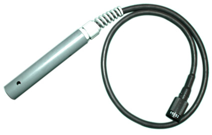
It is recommended that additional reference electrodes are located at these critical areas with a facility to have one of them control the system if required. Existing electrodes can be used for monitoring rather than control. It is also a good idea to use dual-element reference electrodes (Fig. 5 below). The standard electrodes provided are normally not expected to last 15 - 20 years. The dual-element electrodes combine accuracy of silver/silver chloride sw (Ag/AgCl) with the long-term reliability of Zinc sw (Zn).
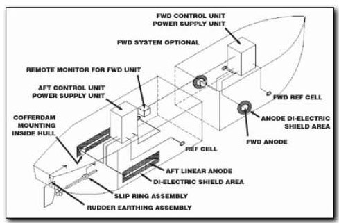
Figure 3 - Typical Ship ICCP layout (courtesy of Cathelco UK)
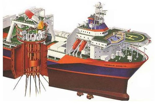
Figure 4 - Typical FPSO turret detail (Courtesy Statoil)
So, what is good data? The best way to answer this question is to first consider what the typical trend of CP measurements should be; then, compare this to real data. For a sacrificial CP system, when taking measurements with a silver/silver-chloride reference cell, the timeline is something like this:
• The instant the equipment is submerged, the bare metals are unprotected. The CP readings of bare carbon steel would typically be -600mV to -650mV.
• As the CP electrochemical process occurs, the CP readings move toward the protected range, which is more negative than -800mV.
• In time, perhaps a month or more from immersion, the CP reading becomes reasonably static. A well-protected structure would have a CP value around -950mV.
• This CP level remains reasonably stable over the bulk of the life of the anodes - typically 15 to 20 years. There will be minor changes, around +/- 25mV, caused by several factors that include reading inaccuracies. These minor fluctuations are not serious and are to be expected.
• As the anodes reach the end of their lives, they put out less current and, consequently, the CP levels reduce exponentially.
• As a rule of thumb, retrofit CP is needed once the CP level drops to -850mV. The objective is to replace the anodes before the item becomes unprotected.
In summary, the data graph should show an initial rapid increase in CP level, followed by a prolonged period of slightly fluctuating readings, and ending with a decay curve that leads to under-and-then-no protection.
Now, when one looks at some real-life data, there can be challenges. A set of readings taken on an item of subsea equipment using an ROV fitted with an industry standard contact CP probe illustrates the potential challenges. The problems included the following:
• At any given test point, the year-on-year data varied wildly – much more than the generally acceptable +/-25mV fluctuation. The lines of data should lie on top of each other, within a +/-25mV fluctuation, or show a progressive decay from inspection to inspection point.
• It is permissible to have variations in CP from place to place on one entity. CP is never totally uniform. If the variations are true changes in CP, they should be reasonably consistent year-on-year.
• One dataset dropped dramatically and indicated under-protection at multiple points. Then, another dataset jumped back to the general range of earlier sets. It is all too easy to say that one set is the bad apple, but there’s no way of knowing for sure without another inspection.
It is very likely that the inspections were performed by different crews and ROVs. They may not have had the previous inspection results available, leaving them without a reference point. In the ideal world, this is not relevant. Good operators with good equipment should achieve good data. The problem is that there are many factors, beyond the scope of this article, that justify the data.
The main point is that data like this does not conclusively prove that the corrosion risks are being well-managed, and there must be a better way of monitoring the CP status of critical and expensive subsea infrastructure as part of a risk management plan.
Permanent CP monitoring
Permanently installed CP monitoring is not new. As early as 1972 there have been permanent monitoring systems in offshore platforms. Deepwater Corrosion Services has been involved in providing monitoring equipment since the mid-1980s, with permanently installed zinc reference electrodes on Gulf of Mexico structures. These older systems only worked on fixed or floating structures, as monitoring was done topsides.
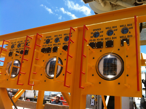
Since then, the company has developed a vast improvement to this early technology with the solar-powered monitoring system that allows for consistent and reliable measurements at the locations where integrity risks are their greatest. The system only requires the ROV’s lights and camera to take the measurements. This system has been successfully installed at various locations, including Shell’s Olympus field in the Gulf of Mexico.
Solar-powered system
The fully self-contained monitoring system consists of two primary elements: the reference electrodes and the test panels.
The reference electrodes are zinc because of their stability and proven longevity. These are installed at points on the equipment/structure where corrosion risks are at their greatest.
The test panels are fixed to the structure at locations accessible to the ROV. They contain voltmeters powered by the photocells to measure the CP potentials. In the event of electrical/electronic failure, the test panel has stab plates where the ROV can take conventional probe readings.
Once installed, taking readings is straightforward. As the ROV approaches the test panel, its lights activate the solar panels under the glass domes. The power generated brings the voltmeter and ammeter to life. The CP potential and current are displayed on the gauges at the top of the panel, which is captured by the ROV camera. In addition to the consistency and repeatability of readings, this is a fast scan system that significantly reduces ROV work time.
The benefits of the system seem to be self-evident. Even so, there appears to be a need for a paradigm shift in the offshore industry before this technology is widely accepted.
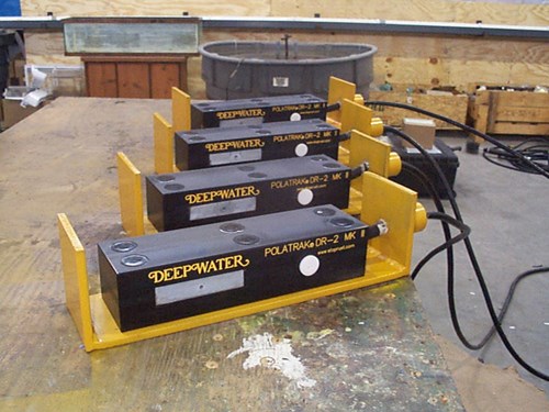
Figure 5 - Permanent dual element reference electrode (above)
(newer model info available here) SunStation solar-powered test panels (below)
Stray current interference - Whenever an impressed current CP system is used offshore it is important to be aware of potential interference sites. In certain instances, cathodic protection currents can be picked up inductively on steel surfaces and subsequently discharged back through the seawater to another part of the structure. At the point of discharge localized corrosion can result. In order for this to occur, the affected structure must be within the field gradient of the anode. It must also be electrically isolated or connected through a high-resistance path to the main cathodically protected structure. For example, on pipelines associated with fixed platforms, the location of impressed-current anodes protecting the structure must be such that the isolated pipelines do not lie within the close field of the anodes, otherwise there is a risk of current jumping from the pipeline riser to clamps attached to the structure. On an FPSO, this risk may exist on mooring components close to the hull, or on mechanical couplings associated with the risers within the turret structure. Modeling of anticipated voltage gradients at maximum rated anode output will facilitate the prediction of potential problems.
Sacrificial anodes - If the vessel is a newly built FPSO, then a life-cycle economic comparison will almost certainly favor the use of galvanic anodes over impressed current cathodic protection (Fig. 7 below). The main reasons for this are:
1. The designer's ability to confidently craft the sacrificial system for 20 year + life.
2. The fact that on a sacrificial system, no maintenance is required.
3. Sacrificial anodes are highly reliable.
4. No modifications are required on the hull interior, and no hull penetrations must be made installing the system.
5. There is no risk of interference.
6. A sacrificial system is compatible with the other cathodic protection systems on the subsea equipment.
7. The life-cycle cost of sacrificial anodes is considerably less than the ICCP option (includes maintenance).
The sacrificial anodes selected are normally platform-sized anodes, weighing 350 - 500 lb. (160 - 230 kg), modified for flush-mounting. Aluminum alloys are preferred, as they are more efficient and lighter weight.

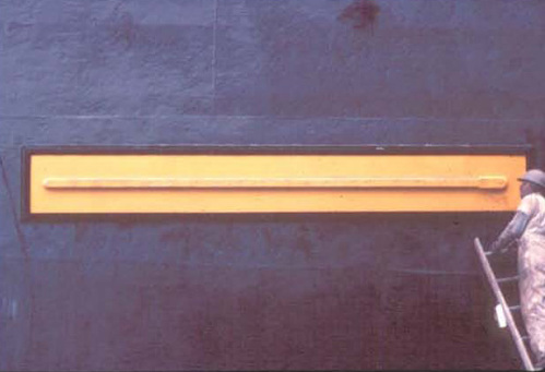
Figure 6 - Typical hull-mounted ICCP anode - Primary dielectric shield
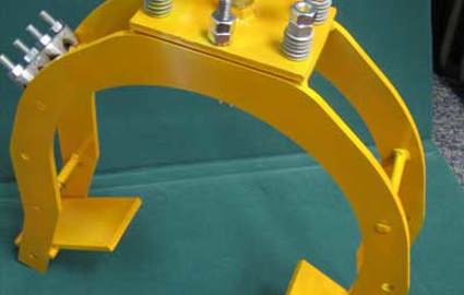
Retrofit systems - With approximately 70 FPSOs currently in operation or under construction worldwide, there are inevitably some vessels that require cathodic protection retrofits. One such FSU vessel operating offshore in West Africa is being studied for application of a new type of impressed current retrofit system. The original sacrificial anodes are virtually depleted, and offshore replacement of the depleted system would be cost prohibitive due to the extended amount of diving activity required. Economic studies of various types of retrofit system have shown the remote buoyant anode system to be the most favorable. The replacement anode sleds sit on the seabed and feed cables are deployed in a "Lazy S" configuration to the surface. The FSU in question is spread moored and is thus particularly suited to this strategy. The advantages of this system are:
1. Anodes (2) are at a remote location, and thus current distribution can be expected to be very uniform over all the protected areas of the vessel and its appurtenances.
2. There is no risk of stray current interference with remote anodes and no local high voltage gradients.
3. Installation can be accomplished in one or two days using only ROV support.
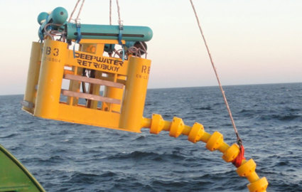
4. Only two such sleds (400 Amperes output each) are required. Installation is planned for 2003. A typical buoyant sled of the type to be used is shown Fig. 8 (below).
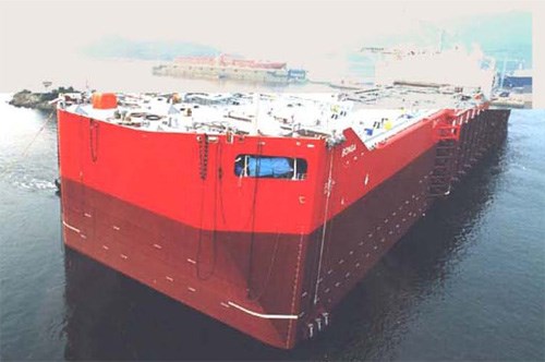
Figure 7 - Sacrificial anodes on the hull
Recommended strategy - For any vessel whether new-build or conversion, the recommendation would have to be for a sacrificial anode system if the expected on station life is greater than 10 years. This recommendation will be supported by both economic and reliability studies. For depleted systems requiring offshore retrofit the recommendation will usually be to deploy impressed current. If the system is allowed to "weather vane" 360 degrees around a turret, a deep-suspended system would almost certainly be the most cost-effective. If full 360-degree rotation is limited, or the vessel has a spread mooring, then the seabed-deployed system will usually be the best option. We can see little if any justification for keeping a close fitted impressed current system on what is essentially a floating production system.
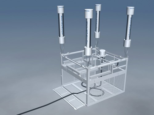
Figure 8 - Buoyant Anode Sled (400 Ampere) Shown With Cable Dispensing Hopper
(Deepwater's RetroBuoy System shown)
Tanks
On an FPSO, tanks can be employed in a variety of different services including, seawater ballast, void, produced water storage and wet and dry oil storage. As with other parts of the CP system, the main issue facing a designer is the longer life requirement, and also the difficulty of entering the tanks for inspection and maintenance while the vessel is in operation. The use of dehumidification systems is becoming more popular for protecting void tanks, but for the remainder, coatings and cathodic protection are the norm.
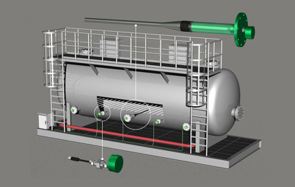
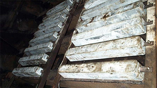
Zinc or Aluminum Anodes? - Our company was recently engaged in the offshore retrofit of an FPSO tank that was in produced water service; temperatures were around 160ºF (70ºC). The tank coating system was badly degraded and the anodes in the tank were heavily depleted. There was some concern about using aluminum anodes in certain areas of tank due to the risk of sparking if the anodes were to fall off; zinc anodes were preferred. But in this particular case the only choice was aluminum because the zinc anodes would have probably passivated in these tank fluids. Indeed, the aluminum anodes had to be carefully alloyed (Table. 1 below) to optimize their galvanic capacity, as they tend to fall off rapidly with increased service temperature above about 140ºF (60ºC). The anodes were deployed on rack-type structures (Fig. 9 below) that were assembled inside the tank and attached with mechanical connections; this was necessary because of the limited access and the inability to perform hot work with the vessel in service. In addition two permanent reference electrodes were installed to aid in monitoring the system.
Table 1
AlZnIn Chemical Composition Modification for Produced Water Service
 |
|||||||||||||||||||||||||||||||||||||||||
Caution - Whenever a retrofit is planned inside a tank with a degraded coating, it is important to consider the rate of hydrogen build-up in the tank from the corroding anodes. This is particularly risky for tanks that have a small ratio of void space to filled space, tanks that are often filled and emptied, and tanks with limited or restricted venting. Before embarking on such a project, calculate the volume of hydrogen that will be discharged during the worst case scenario (i.e. when tank is being quickly refilled after having been empty). If the potential hydrogen concentration approaches the lower explosive limit, then the use of soft coatings should reconsidered. This will reduce current demand and hence the volume of hydrogen produced. This was not a problem on the aforementioned tanks, which never exceeded 75% of fill.
Monitors - Permanent reference electrodes are always almost recommended in a cathodic protection system of this type. In ballast tanks, the most reliable electrode is a zinc sw. electrode. A low-cost field-installed electrode system has been developed for this purpose (read more about TankGard™). Electrodes can be easily routed in the tanks and may be built to length offshore. Routing through a deck penetration allows the tanks to be monitored with no hatch removal or tank entry required.
Mooring systems
General - Most mooring systems for FPSOs include an upper chain section that may include some jewelry to control the catenary angle. This is usually connected to a wire rope taut catenary section that covers the majority of the water column. A further section of chain is often used to connect the taut catenary to the anchoring device. Fairleads or bending shoes are usually attached to the turret structures to control the attitude of the mooring lines.
Pitfalls - The following section identifies some areas where we have been asked to investigate corrosion problems. It also contains recommendations to ensure that the moorings are not compromised by corrosion damage.
Fairleads - The fairleads are designed to allow movement, and they have a number of mixed materials in the bearings and swivels. The main caution for a CP designer is to ensure that the fairleads are electrically continuous with the structure to which they are attached. If this is not checked, anodes provided on the cheek plates of the fairleads maybe prematurely consumed due to current losses to the chain. Afterward, localized corrosion may result in the bearing areas. If properly grounded with a flexible cable jumper, the turret or hull cathodic protection system can accommodate current losses to the chains, while maintaining protection for the fairlead components.
Chain connectors - Like the fairleads, the connectors between chains and rope sections have various mixed metals that can result in a localized galvanic attack (often on chain links adjacent to the connector plates). It is therefore important to ensure that an adequate weight of anode material is attached directly to the connector assembly and that there are no electrically isolated components. Jumper wires should be used across all mechanical joints. A good rule of thumb is to allow for current drain to approximately 100 feet (30 m) of chain in each direction.
Chains - Chains are notoriously difficult to cathodically protect and are therefore normally provided with a corrosion allowance. The biggest problem is that they drain some current from the cathodic protection systems on other components to which they are attached. It is important to allow for this drain by providing additional anode weight.
Wire ropes - The large diameter spiral strand rope commonly used on FPSOs will normally have its own corrosion protection scheme that may include blocking compounds, sheaths, sacrificial anode strands or galvanic coatings on the strands. It is preferable to use sheathed rope (instead of non-sheathed) and to use Zn / Al alloyed coatings on the strands rather than just galvanized. Always ensure that there is adequate anode material and a good quality coating on the wire rope connectors.
Summary
Day one deployment - From a cathodic protection standpoint, it is wise to think of FPSOs as floating production structures rather than ships. With this firmly in mind, the cathodic protection system can be designed in much the same way as one would approach a Tension Leg Platform (TLP) or a SPAR type structure. These structures are somewhat more complex than the average FPSO, but have many of the same attributes on a larger scale. Unless there are very good reasons why an impressed current system must be used, we recommend sacrificial anodes as the most reliable and cost-effective long-term option.
Note: It is important to ensure that there is electrical continuity through various mechanically connected components, and that all systems are compatibly designed.
Anode retrofit - In the event that a cathodic protection system needs to be replaced offshore, we would recommend consideration of impressed current deployed remotely from the hull.
Want to receive an email when Deepwater publishes new corrosion-related technical papers, case studies, and more? Sign up for our Corrosion Newsletter using the form below. You can unsubscribe at any time.

