Technical Paper
Cathodic protection monitoring of subsea pipelines in the Arctic Ocean
by John P. LaFontaine, Todd C. Cowin, John O. Ennis (2000) from Materials Performance Magazine

Abstract
The introduction of subsea pipelines in the Arctic Ocean has provided an opportunity to collect accurate steady state polarization data in this environment. In order to record this data, a cathodic protection monitoring system was designed and installed on a recently built pipeline in the Beafort Sea. The system includes sensors to measure a range of parameters including anode current output, pipeline potential, current density and temperature. The layout, design approach, and results are discussed.
Introduction
Recent advancements in technology and construction techniques have led to the first use of warm buried submarine pipelines in the Alaskan Arctic. BP Exploration Alaska, Inc. is presently developing the Northstar oilfield 6 miles offshore the Alaskan Beaufort Sea coast. Processed crude oil from the Northstar Production Island, known as Seal Island, is shipped via a 10-inch buried subsea pipeline 6 miles to a shore crossing at Point Storkersen and then an additional 11 miles overland to the Trans-Alaskan Pipeline System (TAPS) Pump Station 1 (Figure 1).
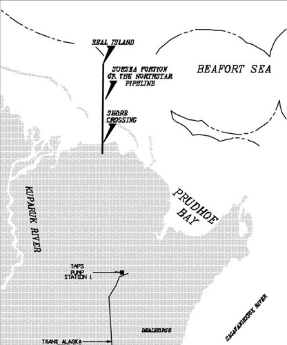
Figure 1 - Area map of the Northstar oil field
Fuel gas will be transported out to Seal Island via an identical 10-inch pipeline, which is bundled to the oil pipeline in the offshore section of the pipeline route. The first time use of such technology in this environment required a conservative corrosion protection system design. As an added measure of this approach, a cathodic protection monitoring system was designed and installed on the oil line to confirm that the pipelines are adequately protected for the life of the project.
It is common knowledge that cathodic protection (CP) is necessary to limit corrosion on metallic structures in marine environments. In addition to conventional CP potential monitoring, valuable data can be provided to owners and operators regarding:
1. The level of protection
2. The remaining service life of the system
3. Potential for improvements to future designs
Field data on the performance of cathodic protection systems for offshore structures and pipelines in the Arctic Ocean is very limited. As a result, it was helpful to monitor a range of parameters affecting the Northstar system performance. These include, anode current output, anode potential, temperature, pipeline potential, and current pickup by the pipeline.
Corrosion protection design
Corrosion protection is incorporated in every aspect of the Northstar pipeline design. Both the gas line and oil line wall thickness are 0.594 inch (15.1 mm) to handle the unique environmental loads of the shallow water Arctic Ocean. The coating system on both pipelines is a dual-layer fusion-bonded epoxy (FBE). The inner coating was a 12-mil (305 mm) anticorrosion layer, the outer coating was a 28 mil (711 mm) abrasion-resistant layer. Each layer was a different color, which allowed mechanical damage after holiday detector inspection to be easily found by visual inspection.
Cathodic protection
An identical sacrificial anode cathodic protection system was used on both pipelines. Impressed current was not a viable option due to the difficulties in establishing an effective ground bed in the permafrost, as well as permafrost’s high ohmic resistance. The CP system was designed according to Det Norske Veritas (DNV) recommended practices for submarine pipelines (1). The system incorporates aluminum-zinc-indium bracelet type anodes designed to incorporate 5% mean and 7% final coating breakdown over the 20 year design life of the pipeline. The low temperature anode chemistry employed for this design is a modification of the standard used for ambient temperature applications (2). This was necessary to account for the effects of cold temperatures on activation of aluminum. The anode design is one 104 lb. bracelet spaced 360 feet apart, or 1 every 9 joints (3).
Cathodic protection monitoring
The strategy for monitoring the Northstar CP system was to design and install fixed monitors on the oil pipeline, supplemented by periodic (3-5 year) portable instrument-survey monitoring. The monitoring system was implemented on the oil line only due to the pipelines being identical. Due to a yearly average of seven months of ice cover, fixed monitoring was the primary focus of the program.
General layout
The fixed instruments were arranged between 500 and 600 feet north of the shore crossing. The instruments included a monitored anode, current density monitor, and reference cells for the pipeline. Each instrument was hardwired to a monitoring panel located at the shore crossing. The pipeline in this region was laid in a trench and backfilled. Safety and logistical concerns required that the instrumentation be installed on the pipe prior to the laying operation. In order to achieve this requirement, each fixed instrument had to be designed to a high degree of redundancy and ruggedness. Accordingly, the signal cable was designed with extra steel armor, protected by an outer non-metallic jacket capable of maintaining its mechanical integrity during pipe lay and backfill.
1. Reference cells - In order to verify the electrochemical potential, each fixed instrument was fitted with a dual reference electrode array. The array is comprised of Ag/AgCl (silver / silver chloride) and Zn (zinc) reference cells. The dual cell package provided a measure of redundancy, as well as a calibration capability. The reference cells, particularly the Ag/AgCl electrodes were designed with a high degree of ruggedness, without compromising contact with the mud. In order to achieve this, the cells were fitted with large semi-permeable membranes, which retain a constant chloride concentration around the Ag element. The bulb was protected from mechanical damage by a non-metallic sleeve.
2. Temperature cells - Temperature sensors are also part of each fixed instrument. These sensors are integrated circuit temperature transducers that produce an output current proportional to absolute temperature. The data acquisition panel supplies power, and output current is passed through a resistor. The voltage drop is measured across the resistor and then translated to temperature.
Monitored anode
One anode was interfaced with an instrument package to verify performance. The package was designed for measurement of anode current output, potential and temperature. The anode was assembled around the pipeline with a layer of neoprene between the anode and the pipe (Figures 2 and 3). The anode was grounded to the pipe through the instrument, allowing for the current to pass through a shunt before returning to the anode. The signal wires for the shunts as well as the other sensors were bundled in a single, heavily armored cable, which was bundled with the pipeline and run back to the monitoring panel at the shore crossing.
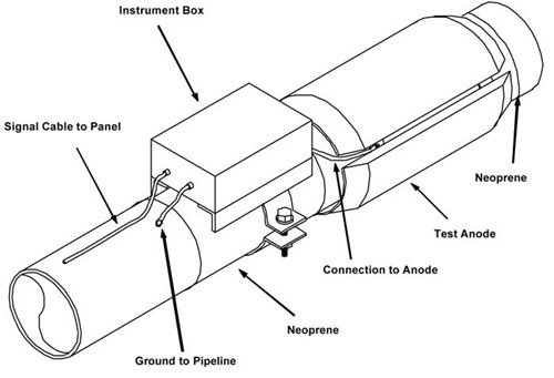
Figure 2 - Schematic of monitored anode setup
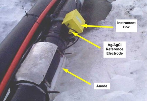
Figure 3 - Monitored anode assembly prior to burial
Current density monitor
The efficiency of the coating system and the influence of environmental conditions on the CP system can be evaluated by measuring current density on the pipe. Coupons, representative of the pipe were instrumented and mounted on the pipeline to measure current density (Figures 4 and 5). The coupons were fastened around the pipe with a layer of neoprene beneath which acts as a dielectric shield. By isolating the coupons in this manner, all the current pick up on the coupons could be shunted thru the instrument, allowing for measurement. The instrument also measured the potential of the coupons as well as the local temperature.
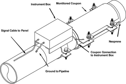
Figure 4 - Schematic of current density monitor setup
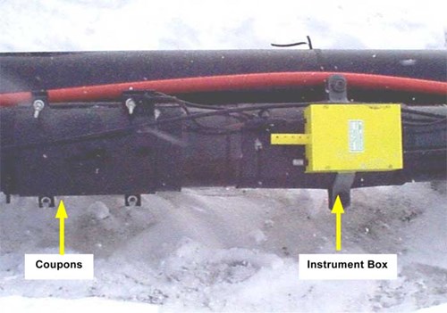
Figure 5 - Current density monitor prior to burial
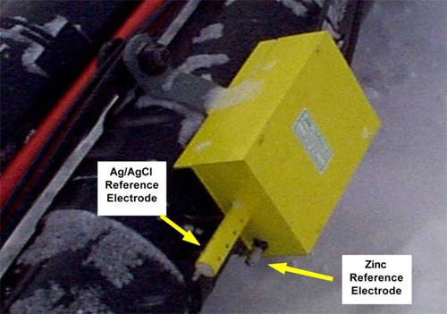
Figure 6 - Permanent reference cell assembly prior to burial
Permanent reference cell
The purpose of the permanent reference cell is to monitor the potential of the pipe (Figure 6). The instrument was placed at a station mid-way between anodes. This area was selected, as it is the most remote from a voltage source. The instrument package contains a Ag/AgCl and Zn reference cells as well as a temperature sensor.
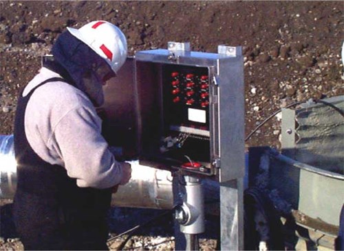
Figure 7 - Cathodic protection monitoring panel near shore crossing
Monitoring panel
The signal wires from the fixed instruments were bundled with the pipeline and terminated at a monitoring panel (Figure 7). The monitoring panel allows for interrogation of the instruments with a hand held voltmeter. In addition, test leads running from the isolation flanges of both pipelines terminate in the monitoring panel, allowing for easy confirmation of isolation.
Seal Island approach
At the Seal Island pipeline approach a test station was installed. The test station provides ground attachments for interrogation with portable reference cells, without having to damage the coating. Additionally the test station can be used to confirm that both pipelines are electrically isolated from the production facilities.
Results
1. After pipe lay and backfilling, functionality tests on all sensors were performed. Initial readings from the system after installation indicate the CP system is working optimally.
2. The temperature measured at the instrument locations ranged from 26 °F (-3.3 °C) to 28 °F (-2.2 °C). Despite the cold temperatures, the environment around the pipe is liquid. This phenomenon is due in part to the hyper saline nature of the sea mud. In addition, the trenching operation may have allowed for seawater to enter the trench surrounding the pipe. Further, the backfill operation required that recently excavated (wet) material be used for the first 2 feet of backfill. This temperature range correlated with geotechnical data for this region.
3. The current output from the test anode was below 0.00001 amps. The anode potential was measured at (-) 1.087 Volts vs. Ag/AgCl and (-) 0.031 vs. Zn. These potentials indicate that the anodes have activated and are operating as designed. The low current output indicates that the coating system is operating at a high degree of efficiency.
4. The pipeline potential was measured at (-) 1.068 V vs. Ag/AgCl. The very low anode current output combined with the near anode potential of the pipe indicates that the CP and coating systems are working as designed.
5. The current density on the coated current density coupons was too low to be measured. The potential of the coupons was (-) 1.065 Volts vs. Ag/AgCl and (-) 0.014 Volts vs. Zn. The very low current pickup and near anode potential of the coupons indicates the efficiency of the coating system to be near 100%.
Conclusions
The data collected by the monitoring system has provided evidence that the Northstar corrosion protection system is working at a high level of performance. The approach used on the Northstar pipeline has confirmed that corrosion protection can be achieved to a high level of performance on pipelines in submarine arctic environments
Acknowledgements
The authors would like to thank BP Exploration – Alaska and INTEC Engineering for permission and support in producing this paper,
References
1. Det Norske Veritas (DNV) Recommended Practice B401, “Cathodic Protection Design”, 1993.
2. J. N. Britton, “External Corrosion Control and Corrosion Inspection of Deepwater Pipelines”, Proc. Of The Deepwater Pipeline Technology Conference, New Orleans, Louisiana, March 1999, Page 3.
3. INTEC Engineering, Inc., “Cathodic Protection Design, Northstar Development Project, Detailed Design”, INTEC Project No. H-0660.03, Technical Note TN440, Contractor Report Submitted to BPXA Inc. May 1998. FIGURE 1
Want to receive an email when Deepwater publishes new corrosion-related technical papers, case studies, and more? Sign up for our Corrosion Newsletter using the form below. You can unsubscribe at any time.
Related content


Technical papers


