Technical Paper
The need for CP retrofit: Monitoring and CP life extension of offshore pipelines
by Rodrigo Himiob (2010)
 Download this article
Cathodic protection retrofit of a pipeline
It is very important to retrofit pipelines that are coming of age, mainly, pipelines that have reached their original CP design life but will continue to be used for a given number of years. The information required in order to perform a CP life extension consists of the following: pipe diameter, length of pipeline, coating type, the age of the pipeline (construction year), operating temperature, is the line buried or not, water depth, desired life extension (years). Utilizing this information the CP designer can use industry standards to accurately predict the bare-steel surface area (e.g. ISO-15589.2, DNV-RP-F103). Subsequently, the estimated surface area will be used along with the information provided to determine the current that will be required to protect the full length of the pipeline. It is important to have an understanding of the anode system that will be used so that the protective current available can be determined for the specific anode-array-geometry. Once the calculations for current requirement for the pipeline and the output current capacity for the array are determined, the key variable - location of the anode arrays - can be calculated. The distances between arrays are provided as ranges so that final locations can be varied to accommodate for any topographical variance or soil conditions that would not allow for an array to be placed at a given location.
Retrofit systems generally comprise the following major components:
1. Anode array – will provide the required amount of cathodic protection required by the pipeline, this will need to be designed to provide protection for the desired number of years, over the designed section of pipeline.
2. Electromechanical contact – will provide the direct contact between the anode and the pipeline; this is the critical link in the system, and must assure long-term contact without damage to the pipeline.
3. Flexible contact – in the form of a cable(s), provides a connection (return path) between the electromechanical contact and the anode array, thereby completing the circuit.
Anode arrays for offshore pipelines are usually sacrificial anodes; this means that a less noble alloy (e.g. Al-Zn-In anodes) will be electrically grounded to the pipeline (via a cable), and will be consumed (sacrificed) in the benefit of the more noble metal (steel pipeline). The main reason that sacrificial systems are used is because no external power source is required to maintain the system. This is especially true for relatively long stretches of pipelines, where running a power cable would be cost-prohibitive or ultra-deep lines where it would be nearly impossible. Having said this, there are cases in which CP can be provided to relatively short pipelines from structures by intentionally electrically connecting the two structures, or by installing an impressed current cathodic protection system (ICCP) on a structure and ground exclusively to the pipeline. Another way to protect relatively short spans of line is by attaching anode arrays to subsea components (e.g. valves, wells, skids, PLETs, PLEMs, etc.) that are electrically grounded to the pipeline; this in turn could provide the CP life extension to the subsea component as well as to the pipeline.
Retrofits for pipelines have been attempted in various ways. However, the strategy that has proven most successful has been to install electromechanical contact clamps to the pipeline at predetermined locations and then grounding an offset anode array, via heavy cables. Offsetting the anode array improves current distribution along the pipeline. Furthermore, an offset array provides a point of contact for the pipeline; this means that we can take potential measurements of the pipeline in without the need to excavate the same.
External cathodic protection monitoring of an offshore pipeline
External corrosion monitoring of a pipeline primarily confirms whether or not a CP system is working properly, but it can also indicate that a pipeline is depolarizing due to damage to the CP system or because the anodes have depleted (end of design life). CP monitoring systems are installed on both new and existing pipelines to give an idea of how the CP system is operating. External corrosion monitoring is critical to assess the condition of the CP/coating corrosion protection system. It is even more critical as the pipeline approaches the end of its original design life. A well conceived monitoring program assists an engineer in planning and budgeting for a life extension retrofit, by providing a better idea of when it will be necessary.
Contact readings, sometimes coupled with contact-free monitoring, are most commonly used to assess the pipeline condition. These readings are time-consuming and cumbersome to obtain, particularly when sections of the pipeline are buried. As a result, there is significant benefit to be derived from the installation of a fixed permanent monitoring system.
Permanent potential measuring systems can be installed on the sea floor or made to float on the water column at any desired height above the pipelines. These systems would be installed similarly to the way cathodic protection retrofit anodes would be. A direct electromechanical contact to the pipeline is required, and the contact mechanism is equipped with a reference electrode and signal wires to a digital readout system. So the three major components for a permanently installed monitoring system are:
1. Electromechanical contact – will provide the direct contact with the pipeline, this mechanism will need to maintain constant contact with the pipeline and be equipped with a reference electrode, usually zinc (Zn). However, silver/silver-chloride (Ag/AgCl) reference electrodes may also be used for offshore applications.
2. Signal wire – will make the electrical connection between the digital readout and the pipeline (through the contacting mechanism). Two conductors are used; one grounded to the pipeline connection point and the other conductor connected to the reference electrode.
3. Subsea digital readout - is a photovoltaic powered high impedance voltmeter that allows a diver or a camera to view potential readings of the pipeline.
Such a permanent monitoring system would allow fast and easy recording of the CP potentials by either diver, a remote operated vehicle (ROV), or an autonomous underwater vehicle (AUV). Once installed, a simple fly-over of the readout would capture the readings in a fraction of the time it would take to do a site survey by excavating and contacting every location.
Although it might seem as if placing permanent monitoring system is something that is done only on aged pipelines, it is recommended that such systems be installed on new build pipelines as well, so that data is available immediately after pipe lay is complete to establish baseline potentials and protection verification. Furthermore, as time passes and inspections are performed, the value of having a monitoring systems increases as it reduces the cost and the time it would take to perform an external corrosion CP survey.
Monitoring and CP retrofitting
At the time a pipeline’s CP system is ready to be retrofitted, a monitoring system can be integrated, so that two systems are installed during one mobilization. Furthermore, if monitoring is done at every point where an anode system is installed, then the CP potentials can be gathered at these locations. This data gathered at the anode array locations can be put into mathematical models and an attenuation model can be run to assure that the potentials at the center-point between two anode arrays remain more electronegative than (-)800mVAg/AgCl (a potential more electropositive than (-)800mVAg/AgCl would indicate that steel is corroding). Despite this fact, a visual inspection of the line between the two points will still need to be made, which will help in determining if the line has sustained any damage that might influence the CP system in any way. In the event that any damage to the coating has been done, the mathematical models can be corrected and corroborated with a damaged site contact reading.
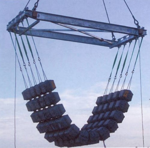
Figure 1 - Deployment of concrete stabilizing mattress with embedded anodes to provide ballasting and cathodic protection to the pipeline.
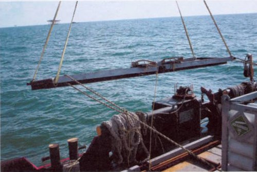
Figure 2 - Deployment of rigid sled anode array for cathodic protection of pipelines. Weight of the anodes is varied depending on the life extension required.
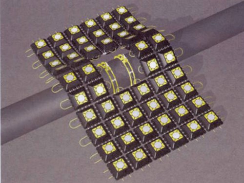
Figure 3 - Concrete mattresses with anodes placed on the pipeline. Void in the center allows for additional snagging or impact protection to the grounding mechanism.
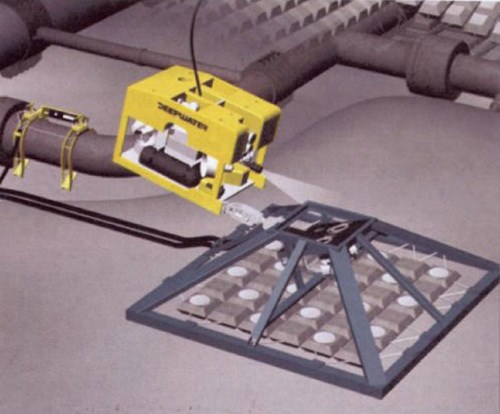
Figure 4 - Over·trawl-able permanent monitoring system. System can be used to monitor any given number of sites from one single location.
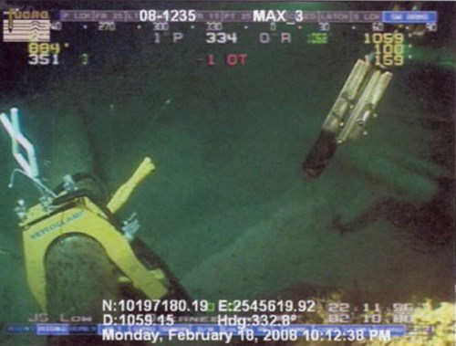
Figure 5 - Electromechanical grounding mechanism installed by an ROV.
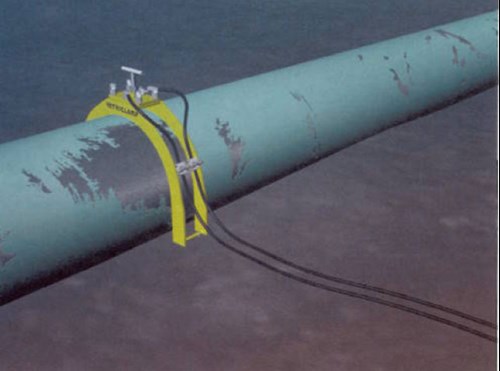
Figure 6 - Illustration of electromechanical grounding mechanisms installed on a pipeline. These systems can be Installed by divers or ROVs.
Related content
Spotlight

RetroPods™ installed on FPU subsea equipment
Wellheads and gravity bases protected by RetroPods™
Read more


Technical papers


